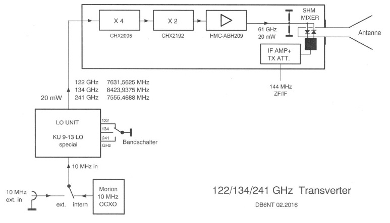
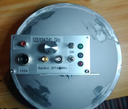
241.920 & (134.928 & 122.250) GHz triband transverter
I use a DB6NT design made by DB6NT.
122.250 GHZ:
Tx output : 0.2 mW SSB
RX NF : 12 dB
241.920 GHZ:
Tx output : <1 µW SSB
RX NF : >25 dB
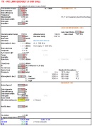
Click on image, download and extract my Excel sheet "Link budget v2.1" to calculate microwave links up to 1000 GHz. Calculation of atmospheric attenuation (ITU-R P.676-12) is included.
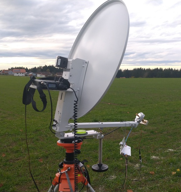
1. Offset or prime focus dish with pan/tilt mount
It depends on accuracy of dish surface (roughness and shape of parabol).
Ruze's equation:
G = -685 * (RMS / Lambda)² ... gain loss due to inaccuracy
RMS ... accuracy of surface
e.g. dish surface RMS = +/- 0.05 mm
G = -0.3 dB @122 GHz
G = -1.1 dB @241 GHz
e.g. dish surface RMS = +/- 0.1 mm
G = -1.1 dB @122 GHz
G = -4.4 dB @241 GHz
e.g. dish surface RMS = +/- 0.2 mm
G = -4.5 dB @122 GHz
G = -17.7 dB @241 GHz
My experience is that a high quality offset dish is much better than a prime focus dish. The reason is that an offset dish has no blocking area due to the feed and the feed sees only the cold sky at low elevations.
Some OE ham colleagues use high precision prime focus dishes (40 cm) made of steel on a lathe (surface accuracy better than +/-0.03 mm). This dish can be used up to 500 GHz without any big losses.
Up to 76 GHz my standard offset dish (63 cm, surface accuracy around +/-0.2 mm) is better than this high precision dish. But at >122 GHz I am losing the advantage of an offset dish.
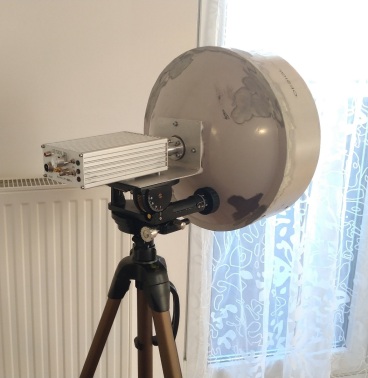
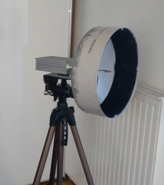
Therefore I use a smaller prime focus dish (30 cm) from a 38 GHz link station at 122 GHz and higher. It has a f/D = 0.3 and focus distance is 90 mm.
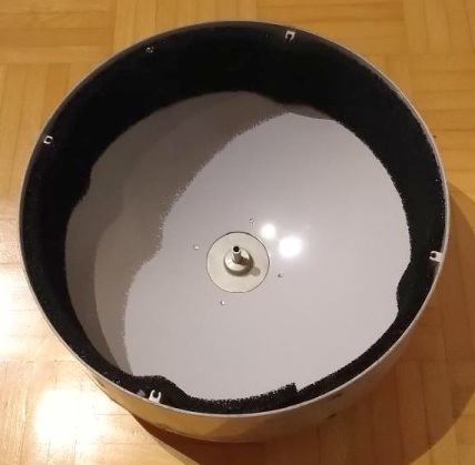
Tripod is a simple one in combination with my old pan/tilt system:
![]()
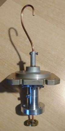
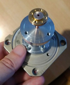
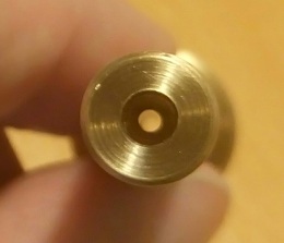
2. W2IMU Dual mode feed horn or "Shepherd's Hook"
At the moment I also use my 122 GHz horn for 241 GHZ with my 63 cm offset antenne.
hdl_ant software by W1GHZ is a good choice to calculate a dual mode feed horn. It is a circular wave guide with a diameter of 1.8 mm and the aperture is 3.8 mm (depth
of 6 mm).
Wave length = 2.45 mm
WR-8 : 2 x 1 mm
With a lathe I made the outer diameter, center hole, dual mode section, flange.
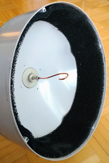
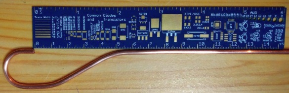
For my 30 cm prime focus antenne I need another feed. I use a copper tube with outer diameter of 3 mm and inner diameter of 2.1 mm. Cut-off frequency is around 90 GHz.
I bended this tube to form a "Shepherd's Hook" with open end aperture to illuminate my prime focus dish perfectly.
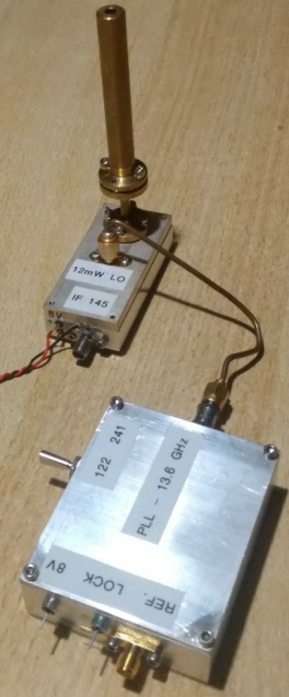
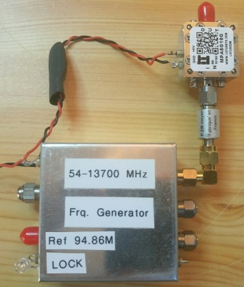
3. PLL with 7555.5 MHz and 7631.625 MHz output
A cheap Chinese ADF5355 board controlled by an Adruino. As input I use an external 94.86 MHz reference signal but it is possible to use internal
reference oscillator.
7.5555 * 32 + 144 = 241920 MHz
7.631625 * 16 + 144 = 122250 MHz
ATTENTION:
As I use a subharmonic mixer we have 2 transmitted sidebands. But that means that we have 4 sidebands at IF and 2 of them are received at same IF frequency (e.g. 144 MHz).
This effect causes degradation of received signal. Without mirror rejection and without 241 highpass filter (as I use a 122 GHz horn) the mixer additionally uses both, LO and LO/2 frequemcy, at 241 GHz.
To overcome degradation of received signal ONE station could change LO freqeuncy by an offset, e.g. 1 MHz.
7.55546875 * 32 + 145 = 241920 MHz
7.6315625 * 16 + 145 = 122250 MHz
8.4239375 * 16 + 145 = 134928 MHz
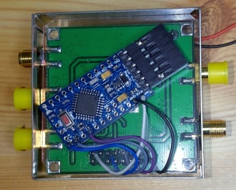
I have done some improvements:
- removed C21, C37 and placed these 2 capacitors between pin2 and 4 of both
voltage regulators
- placed 3300µF/6.3V between J1 and ground to reduce phase noise
- placed a SNA-176 MMIC amplifier in front
of port B (5V goes to 27 Ohm, after that a 1 nF against ground, after resitor a 10 nH to amplifier output, 2.4 pF blocking capacitor in front of port
B) to get approx. 7 dBm output level at 7.6 GHz.
There is an Arduino Pro-Mini 3.3V/8MHz under the synthesizer board. Between both boards there is plastic foil and I use an Arduino input pin for band selection.
To get 11-12 dBm output level (needed by the mixer) I use an additional power amplifier and an attenuator.
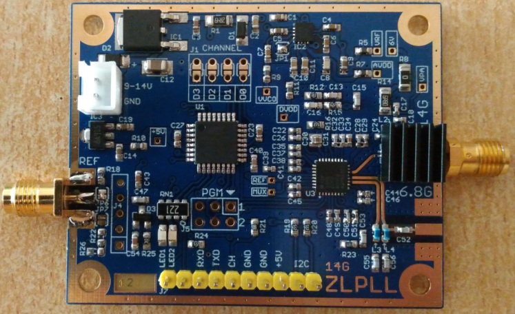
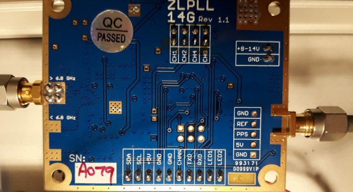
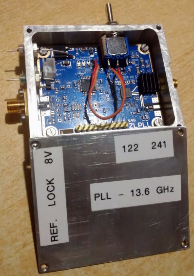
Another solution (my prefered at the moment) is to use the ZLPLL14G made by ZL2BKC. It uses a µ-controller and the ADF5355 too but there is already
a power amplifier on board to get 12-15 dBm output. Additionally it is possible to store up to 16 frequencies and switch from one to another stored frequency within 1 sec. Connection to the board is done via
tera term software. External reference signal (> 10 MHz, 5-14 dBm) is needed and accuracy of output frequency is better than 1 Hz with GPSDO
Current consumption: 300 mA
Modification:
- Change 0 Ohm resistor R8 (power supply output amplifier AVA183 MMIC) against 50 Ohm potentiometer to adjust output power for best Rx/Tx performance
- 122 GHz: R8 = 21 Ohm for 9.5 dBm
- 134 GHz: R8 = 9 Ohm for 11.8 dBm
- 241 GHz: R8 = 18 Ohm for 10.6 dBm
LED2 at bottom side can be used as "PLL locked" signal.
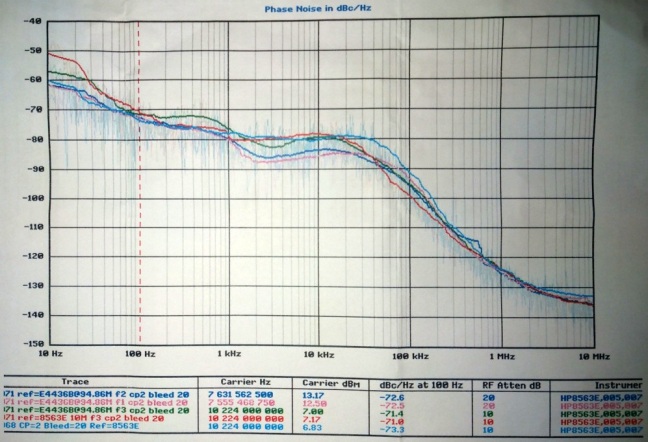
Phase noise:
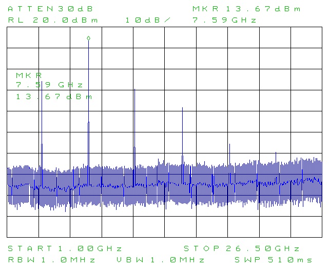
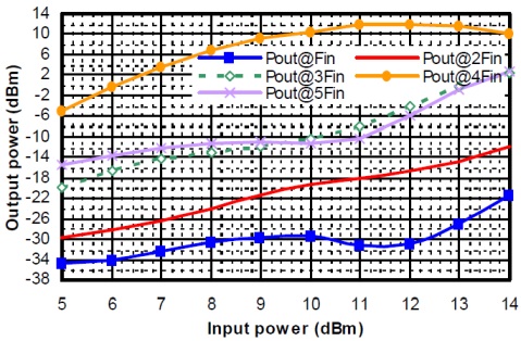
Harmonics:
I made an aluminium housing 70 x 60 x 23 mm for this synthesizer PLL.
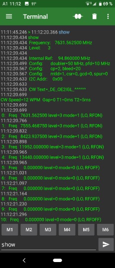
Programming of the ZLPLL14G is done via serial USB terminal software. It is possible to use "Tera Term" in combination with a computer or a smart phone app like "serial USB terminal".
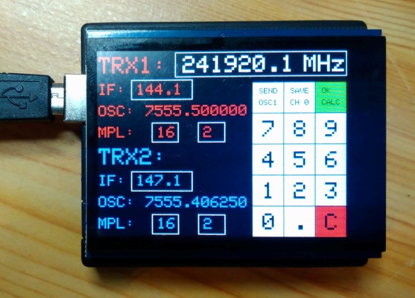
For easier programming of the ZLPLL I made a tool to calculate ZLPLL output frequency depending on RF frequency, IF and multiplier factor for both stations or a beacon. After calculation it is possible to send desired frequency to ZLPLL and save it to a channel.
The tool is an Arduino UNO with a capacitive 2.8" touch screen.
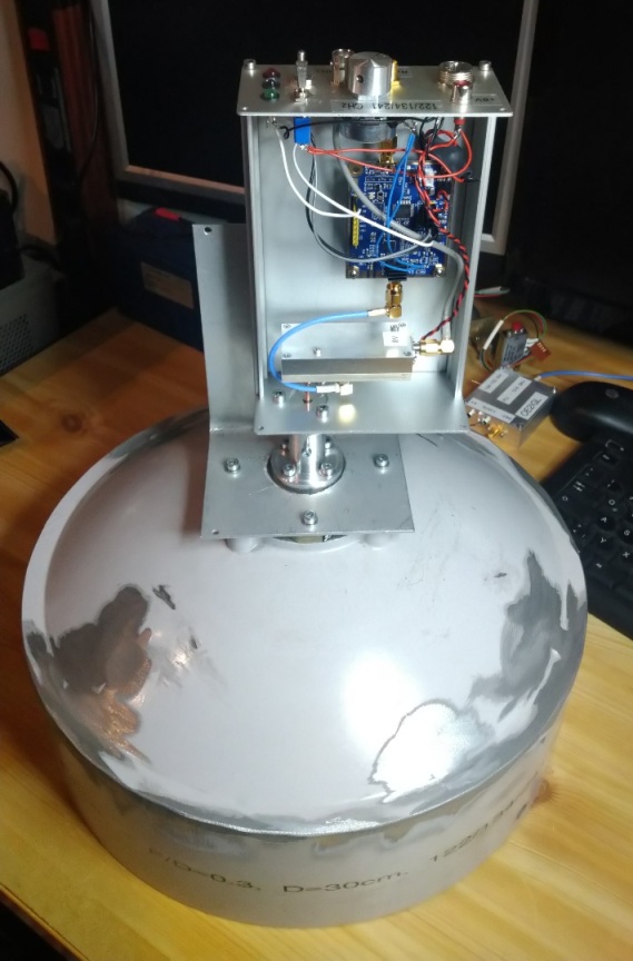
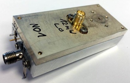
4. Triband mixer & IF interface
This module was made by Michael, DB6NT.
IF Tx-power should be <3 W and LO-power should be around 12 mW. Output is a WR-8 waveguide.
Power supply: 8V
Output power: 0.2 mW @ 122 GHz, <1 µW @ 241 GHz
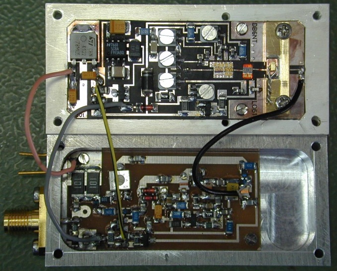
To drive the CHX2095 adaquate the output power from the PLL should be around 11 - 12 dBm.
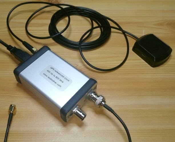
5. GPS disciplined reference oscillator to drive PLL board
Here I use a GPSDO by Leo Bodnar.
It has 2 outputs (3.3V CMOS level) from 450 Hz to 800 MHz and it uses GPS receiver for very stable output frequency.
Output power up to 13.7 dBm
Current consumption @ 12V DC: 190 mA
I use an output of 94.86 MHz to drive PLL board. Therefore I can use same Mini-GPSDO as for my 76 GHz transverter.
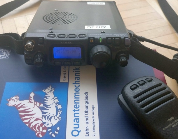
6. IF receiver/transmitter
Therefore I use a FT-817. I have upgraded my FT-817 with an additional IF output. In combination with e.g. SDR# and a Lenovo Convertible Miix 320 Tablet
computer I can find small signals to adjust frequency and dish orientation.
7. Accu pack
I use a 12V LiFePO4 accu with 10Ah because of its light weight, only 1.4 kg.
8. Test results
9th of November 2019: First test with Rudi (OE5VRL) in OE5. 122 GHz and 134 GHz were ok on SSB/FM over a distance of 8.5 km.241 GHz was ok on SSB/FM over a distance of 53m.
At 241 GHz we made the first ever QSO's in Austria (OE). I used my 63 cm offset dish with a dual mode horn for 122 GHz.