76 GHz transverter
As I have collected a lot of 10 GHz knowhow it is time to go to higher frequencies. In 2018 I decided to enter into 76 GHz band.
It is not only a higher frequency band it needs also new knowhow, wave guides are a requirement, active components are very expensive and rare for amateurs, you must consider propagation
loss by H2O, O2...
Here I will explain all technical details of my new 76.032 GHz transverter and I want to thank all microwave pioneers
for their preliminary work. Special thanks to Michael DB6NT, Rudi OE5VRL and Hans OE2JOM who made this unit possible.
Click on image, download and extract my Excel sheet "Link budget v2.1" to calculate microwave links up to 1000 GHz. Calculation of atmospheric attenuation (ITU-R P.676-12) is included.
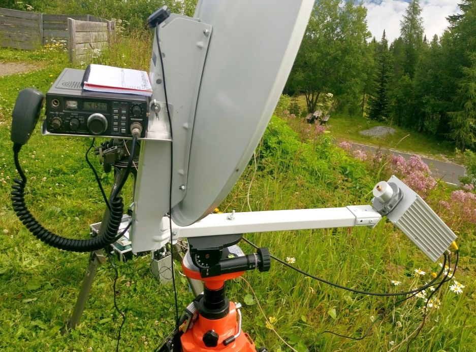
1. Offset dish and tripod with pan/tilt mount
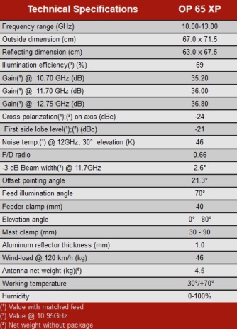
I only use Gibertini offset dishes, in this case model OP 65 XP (675 x 630 mm, f/D = 0.66, dish illumination 70°).
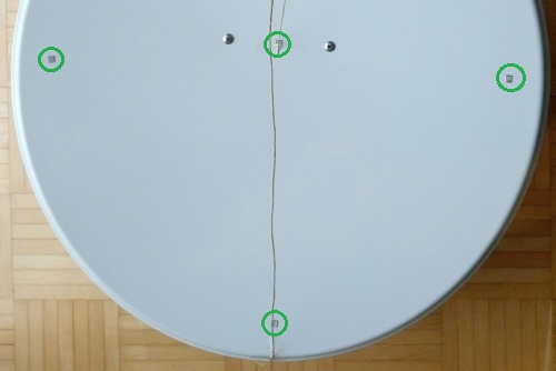
At first I tried to find deepest point of offset dish along long axis. In my case the depth is 52.0 mm
f = shortaxis³ / 16 / longaxis / depth = 630³ / 16 / 676 / 52 = 445 mm ... distance from focal point (blue) to bottom rim of offset dish
offset tilt = arccos (shortaxis / longaxis) = arccos (630 / 676) = 21.3°
-3 dB beam width is 0.4° at 76 GHz.
Gain is approx. 51 dBi at 76 GHz, in reality not more than 47 dBi at this frequency.
To determine the position of focal point I use hdl_ant software by W1GHZ.
Input is long and short axis, max. depth and distance from max. depth to bottom rim.
Output is the distance from focal point to top rim and distance from focal point to bottom rim.
Then I made a knot into a string and measure both output distances from the knot to both ends.
I fixed both marked ends on the dish (bottom and top rim) and then the knot showed me the focal point (blue point).
I got best signal if the focal point is 20 mm in front of feed holder.
Difference between phase center of dual mode feed horn and focal point must be smaller than wavelength/4, in this case better than 1 mm.
To get a very sharp focal point the dish geometry (deviation from parabolic shape) must be better than wavelength/4.
For best illumination of an offset dish the feed should point to the deepest point of the dish. That's not the center of an offset dish!
Again I used a string from the deepest point to the focus point. The string and the feed axis are parallel -> perfect!
blue point ... focal point of dish
green point ... center of dish
red point ... deepest point of offset dish

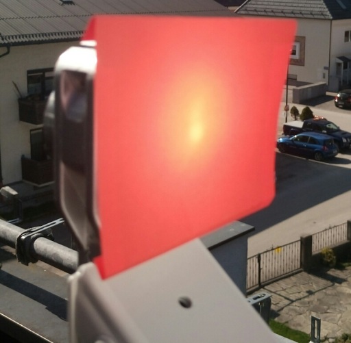
In addition I glued some small pieces of mirror foil on the dish. Then I pointed carefully the dish to the sun and moved a carton in front of the LNB holder to find the
point where all sun reflections accumulated nearly into one point (= focal point).
Again the focal point is 20 mm in front of feed holder. The focal point should be up to 15 mm inside of feed horn aperture.
To find best adjustment of focal point I use sun noise measurement methode. Move the feed in LNB holder until the difference between sun noise and cold sky noise is maximum.
Of course a prime focus dish of a e.g. 37 or 80 GHz communication link station would be the best solution because the parabolic shape is much better.
G = -685 * (RMS / Lambda)² ... gain loss due to inaccuracy, RMS ... accuracy of surface
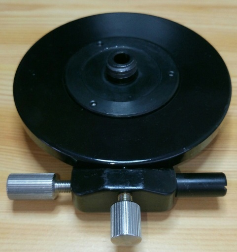
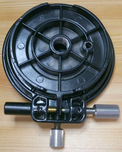
This is my pan/tilt head for my tripod used on top of a tripod. The metal boom of the dish is mounted on the tilt plate.
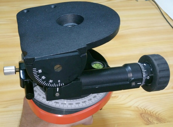
Tilt plate: Fine tuning with knob within 0.1°
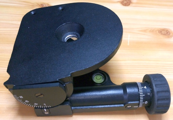
360° azimuth plate with fine tuning screw: Fine tuning is 0.1° within ±5°;.
I use this azimuth plate for sun noise measurements.
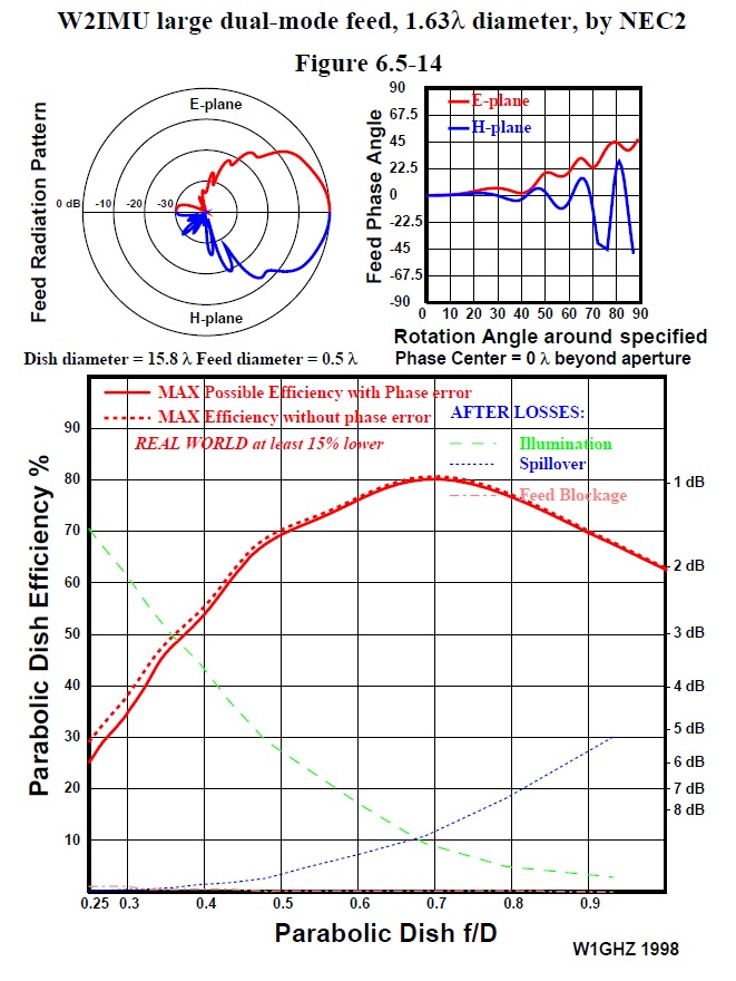
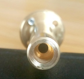
2. W2IMU dual mode feed horn
hdl_ant software by W1GHZ is a good choice to calculate a dual mode feed horn. It is a circular wave guide with a diameter of 3.1 mm and the aperture is 6.1 mm (depth of 9.7 mm).
With a gain of approx. 12 dBi the -10 dB illumination angle is 75°.
I use 1.55 * wave length diameter to get best match to my F/D = 0.66 offset dish.
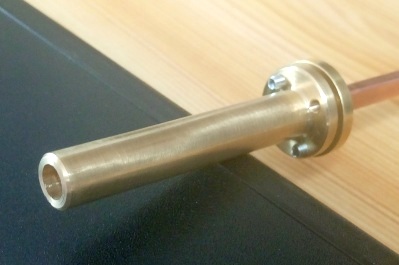
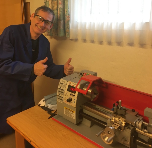
I made this horn with my turning lathe.
Between the rectangular waveguide (wave guide switch) and circular dual mode horn I have inserted a 20 mm long wave guide taper.
WR-12: 3.1 x 1.55 mm
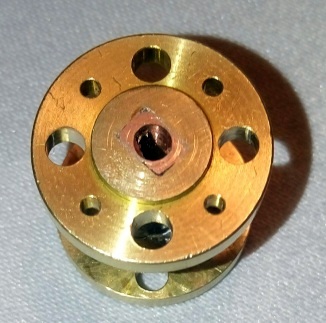
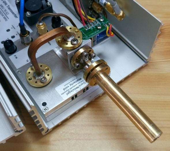
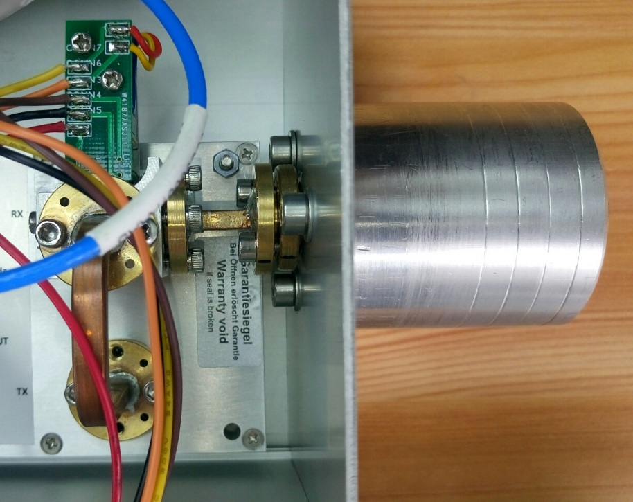
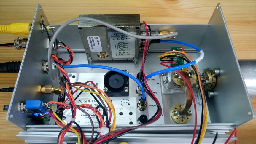
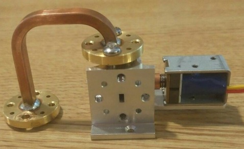
3. Wave guide switch
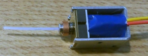
This unit was delevoped by Rudi OE5VRL and Hans OE2JOM. A lift magnet switches between Tx and Rx mode.
RX loss is only 0.3 dB
TX loss is only 0.6 dB
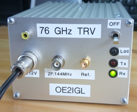
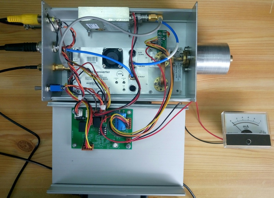
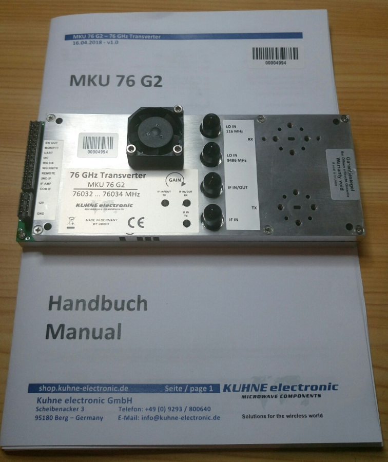
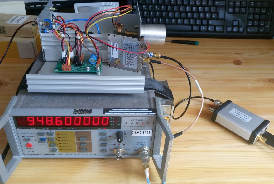
4. Transverter
The transverter is the new 76 GHz generation unit developed by Kuhne Electronics. Thanks to Michael DB6NT and his team for this slim, high performance and state of the art transverter.
Measured Tx power : 320 mW, (270-280 mW after wave guide switch)
Measured Noise figure : 6.3 dB
Current consumption on receive @ 12V DC: 250 mA
Current consumption on transmit @ 12V DC: 830 mA
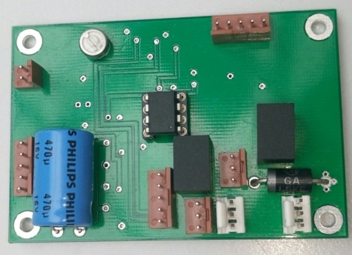
5. Control interface
This unit was delevoped by Hans OE2JOM, Josef OE2IWM and it comes with the wave guide switch.
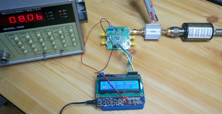
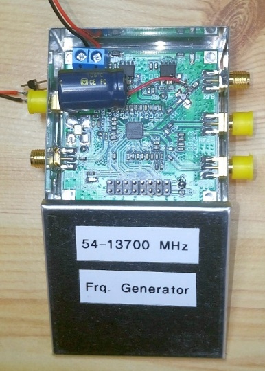
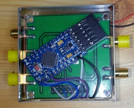
6. PLL with 9486 MHz output
A cheap Chinese ADF5355 board controlled by an Adruino with buttons and a display. See Alan Fort
F1CJN
With the buttons it is possible to select any frequency between 50 MHz - 13 GHz. As input I use my 10 MHz reference signal (from GPS) but it is possible to use internal reference oscillator.
In my case I need 9486 MHz as output that goes into my transverter unit, output level is -3dBm.
After the PLL I connected a homemade 10 GHz amplifier to get approx. 8 dBm output.
Another solution is to build in directly a MMCI amplifier (MGA-86576 or NLB310) between C14 and RFB port.
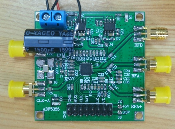
I have done some improvements:
- removed C21, C37 and placed these 2 capacitors between pin2 and 4 of both voltage regulators
- placed 3300µF/6.3V between J1 and ground to reduce phase noise
- placed a SNA-176 MMIC amplifier in front of port B (5V goes to 27 Ohm, after that a 1 nF against ground, after resitor a 10 nH to amplifier output,
2.4 pF blocking capacitor in front of port B) to get approx. 8 dBm output level.
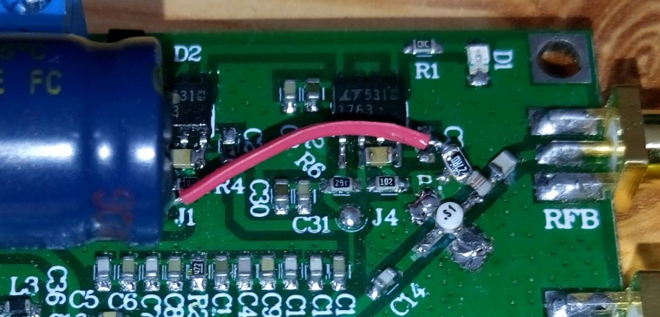
Now there is a Arduino Pro-Mini 3.3V/8MHz under the synthesizer board. Between both boards there is plastic foil.
The best solution is a Herley/CTI PDRO-9371-1 phase locked dielectric resonator oscillator. This module has a reference input and standard output is at 9500 MHz.
A multiple input frequency gives us an output around 9500 MHz. It is possible to retune the output to 9486 MHz, input is then e.g. 94.86 MHz.
Reference input level should be around 0 dBm and RF out is max 15 dBm (31 mW).
Current consumption @ 12V DC: 180 mA
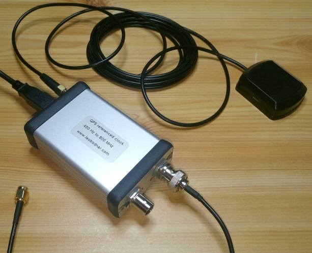
7. GPS disciplined reference oscillator set to 94.86 MHz output
Here I use a nice unit by Leo Bodnar.
It has 2 separate outputs (3.3V CMOS level) from 450 Hz to 800 MHz and it uses GPS reveiver for very stable output frequency.
Output power up to 13.7 dBm
Current consumption @ 12V DC: 190 mA
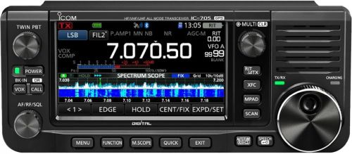
8. IF receiver/transmitter
Therefore I use my modified IC-705 to switch the transverter into TxOut mode.
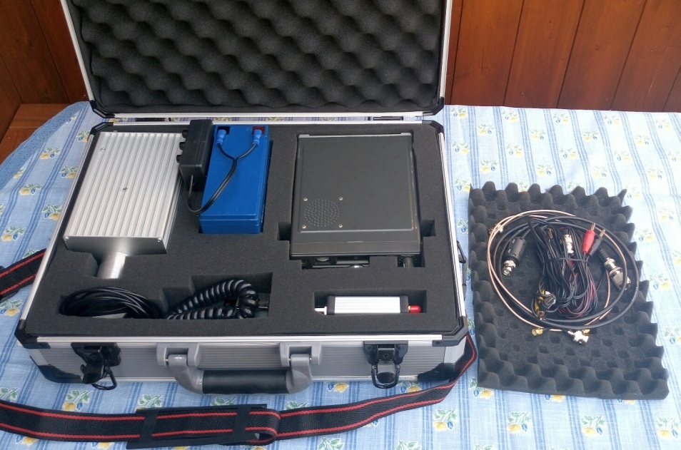
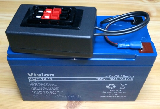
9. Accu pack
I use a 12V LiFePO4 accu with 10Ah because of its light weight, only 1.4 kg.
Power consumption of whole system:
@ receive: 700 mA
@ transmit: 2000 mA
10. SDR signal finder
This could be useful to find 76 GHz signal of opposite station. Signals are very weak and -3 dB beam width is only 0.6°. Frequency of both stations must be very
accurate and stable, with GPSDO it is no problem.
I will use my Airspy/Funcube dongle pro+ receiver and SDR# software to find signal (frequency, elevation and azimuth) of opposite station.
Therefore I bought a Lenovo Convertible Miix 320 Tablet PC (10.1" touch screen), Win10 and only 0.56 kg.
11. Test results
8th of July 2018: First 76 GHz (SSB) QSO between Gaisberg (1280 m, JN67NT) and Hellmonsödt (870 m, JN78DK) over 110 km, no line of sight.
14th of July 2018: Sun noise measurements (sun against cold sky) -> improvement von 0.95 dB to 1.55 dB (need to made some improvements to get more dBs).
15th of July 2018: Microwave day in OE8 Carinthia. QSOs at 5.76, 10.368, 24.048, 47.088 and 76.032 GHz, distance up to 97 km.
16th of July 2018: Again sun noise measurements (sun against cold sky) to improve dual mode horn in focal point -> now I have 4.6 dB
20th of October 2018: "Sun noise measurement day" in JN78DK. Around 8 microwavers measured their
system -> I reached 4.85 dB. Receiver NF is around 6.0 dB, measured with ground - sky methode (0.75 dB).
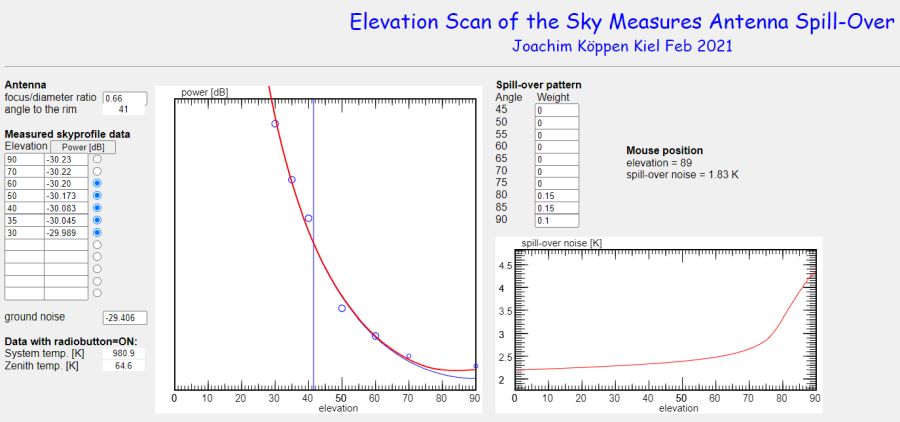
18th of November 2018: Sky dip measurement (= cold sky noise measurement at different elevations) with feed/transverter + curve fit to determine receiver NF ->
6.4 dB (with waveguide switch), 6.0 dB without.
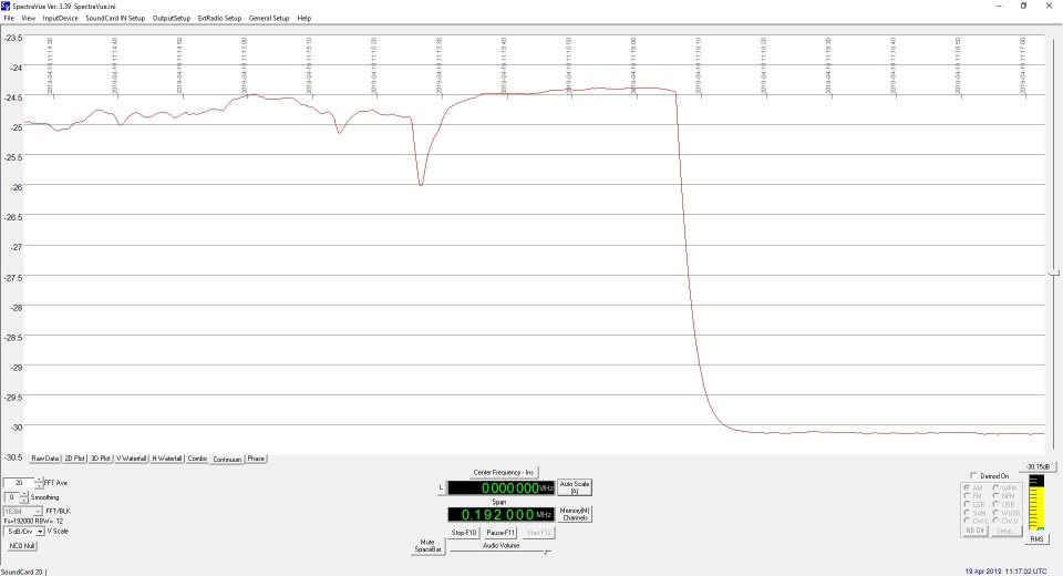
3rd of March 2019: Sun noise measurement: after some adjustments I reached 5.20 dB. Weather conditions 14°;C, 38% humidity, 964 mbar and sun elevation 34.7°.
23rd of March 2019: Sky dips measurement, cold sky measurement at different elevations with the transverter (with wave guide switch and dual mode horn) -> receiver
NF = 6.30 dB (with waveguide switch)
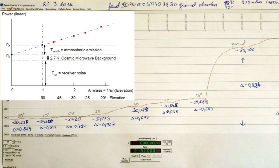
Joachim Köppen DF3GJ has a script to calculate spill-over and system temperature too.
19th of April 2019: Sun noise measurement: I reached 5.78 dB because it was very dry. Weather conditions 22°;C, 22% humidity, 944 mbar and sun elevation 53.2°.