EME link budget characteristics at 24 GHz and higher
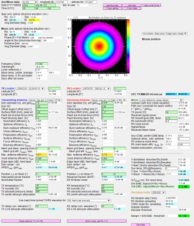
Start EME Link Budget Tool by clicking:
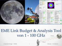
17th of February 2024: Talk "EME Link Budget & Analysis Tool from 1 - 100 GHz" at Dorsten GHz conference in Germany
Click here (only available in German) -->
1. What's the question?
At high frequencies and/or big antennas the half power beam width (HPBW) of the antenna is in the range (or even smaller) of moon/(sun) diameter (FWHM full width at half maximum of 0.5°).
That means that the moon isn't anymore a point source. It is an extended source and all existing formulas in the easy form for radar or EME are not valid and need a correction term.
Starting point is the software EMEcalc by Doug VK3UM (SK) who wrote an excellent software to calculate link budget for EME QSOs and echos.
Because it was written in the times when 10 GHz EME was still standard all calculations were correct. But now 24 GHz EME is standard and 47 GHz EME looks very promising in combination
with weak signal decoding software, EMEcalc isn't as precise as should be.
Missing points:
- The so called "fill factor" is only considered for moon and sun noise calculations. It is not considered for the whole Tx-moon-Rx system (2-way EME) to calculate echo S/N and EME S/N. See chapter 2 to 6.
- At high frequencies and/or big dishes a small antenna half power beam width of much smaller than 0.5° (moon diameter) has another challenge resulting in antenna pointing offset loss.
If both antenna are not pointed at the same moon point then S/N will further decrease as Manfred DL7YC showed us at EME2022 in Prague.
This can be calculated not only for a point source, even for a extended source. See chapter 7.
- Accurate estimation of path loss due to atmospheric gases and sky brightness temperature. See chapter 8.
- Dish surface efficiency (given by Ruze's equation) is not included
Ruze's equation:
G = -685 * (RMS / Lambda)² ... gain loss due to inaccuracy
RMS ... accuracy of surface
e.g. dish surface RMS = +/- 0.05 mm
G = -0.3 dB @122 GHz
G = -1.1 dB @241 GHz
e.g. dish surface RMS = +/- 0.1 mm
G = -1.1 dB @122 GHz
G = -4.4 dB @241 GHz
e.g. dish surface RMS = +/- 0.2 mm
G = -4.5 dB @122 GHz
G = -17.7 dB @241 GHz
Already in 1995 DJ7FJ Josef Fehrenbach1, 2 wrote an interesting article about "What's special about 10 GHz EME?".
PA0EHG Hans extended this article to "What's different on 47 GHz EME?". Because I wanted to understand these outcomes in more detail I decided to investigate some time into fill factor (fill loss).
It was very helpful that I did some sun noise investigations in the higher GHz bands in 2018. At 76 GHz and with a 65 cm offset dish the half power beam width is only 0.5°
and therefore the same size as the sun diameter. The sun is more overlapping the antenna main beam and the antenna side lobes are starting to detect the sun noise too. This is expressed by the fill factor.
Joachim Koeppen DF3GJ made a lot of extremely useful EME tools. Mainly for better understanding what happens at higher frequencies or/and big dishes.
EME tools
2. Radar equation and fill factor
Radar equation for point sources:3
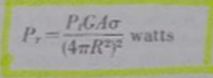
General radar equation:3
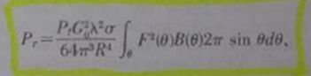
The integral is 1 for point sources but it is smaller than 1 for extended sources. That means we have to calculate the integral for both antenna patterns,
moon pattern and the integral represents the "beam width factor BWF" (= convolution of antenna/moon pattern).
3. Antenna and moon pattern
Antenna pattern:
To solve the integral we need an appropriate antenna distribution. The antenna distribution depends on the feed distribution4.
DF3GJ Joachim has written a script to calculate (real) antenna pattern at a given feed pattern. Usually one of these antenna pattern can be used.
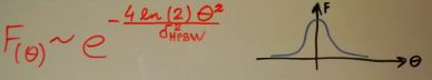
Gaussian circular: This is a common used distribution for a dish.
Uniform illuminated circular dish: A uniform feed distribution results in an antenna distribution defined by the Bessel function5.
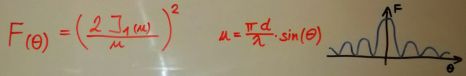
-10 dB taper illumination circular dish: Usually this is the target, a -10 dB taper at the dish edge by the feed distribution. Distribution is again a Bessel function but with lower side lobes5.

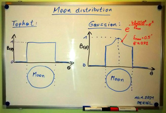
Moon pattern:
The pattern for the moon is easier to define. For frequencies higher than 10 GHz it is more a "tophat pattern" because the reflection isn't only in the center of the moon. Reflection looks like in the visible range.
Some improvements could be done with an adapted "gaussian distribution" (use a taper at the moon edge). UA3AVR Dimitry showed this in DUBUS 3/20166.
Useful antenna formulas5:
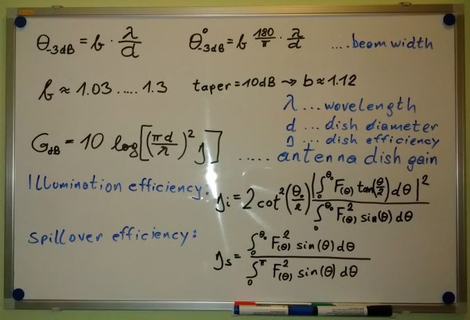
b = 1.269 - 0.566*t + 0.534*t2 - 0.208*t3
feedtaper [dB] = 20 * log (t)
b = 1.22 for Gauss antenna distribution
b = 1.13 for -10 dB taper
4. Solving the integral to calculate "fill factor"
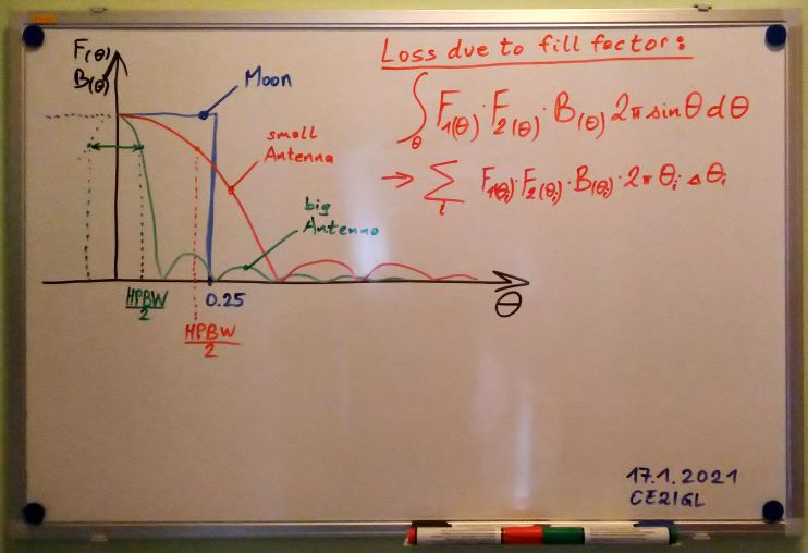
Let us start slowly. At first we will calculate a correcting factor for Rx path (receiver - moon), this is called fill factor.
Instead of an integral we use the sum symbol with fine angle steps. It is easier to solve this using Excel.
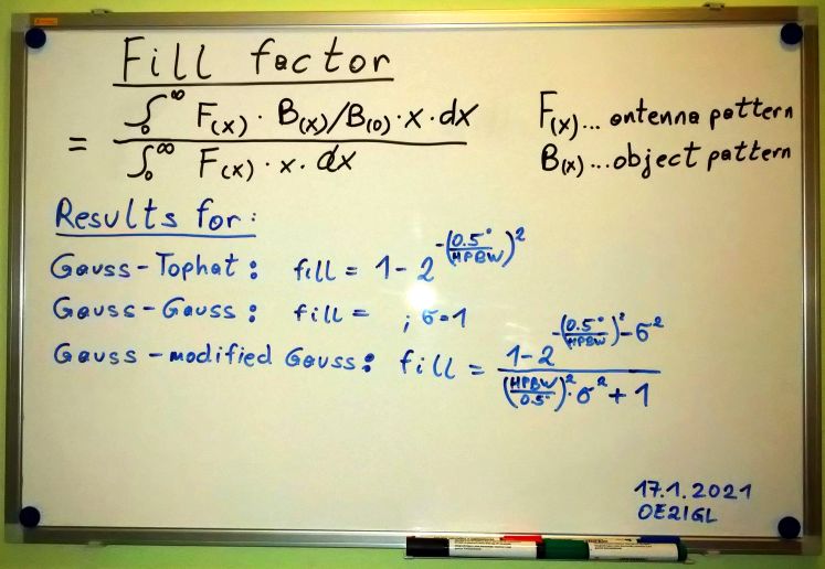
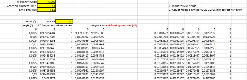

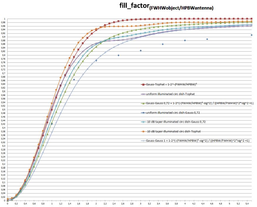
5. Results for different Rx antennas and moon pattern
Fill factor for one antenna and moon/sun. This can be used for moon or sun noise measurement. Moon or sun bright temperature is reduced by fill factor.7, 8
6. Solving the integral to calculate Tx-Moon-Rx "beam width factor" loss for EME
Now we will extend our Rx-moon calculation to the full Rx-moon-Tx path and the resulting correcting factor is called "beam width factor" BWF. On the white board I use a tophat moon pattern and 2 different (for Tx and Rx). This loss exist always!
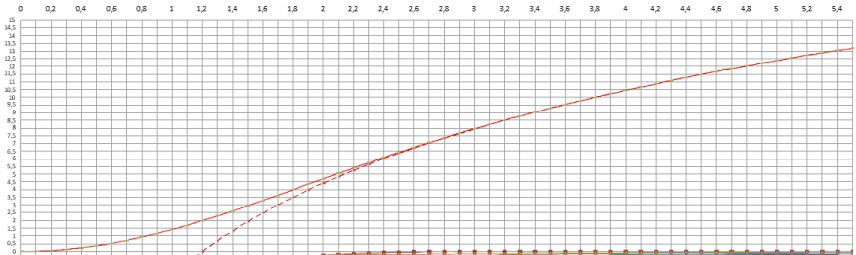
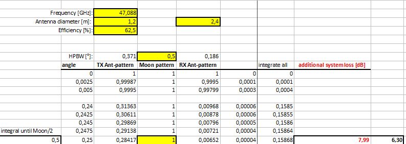
Here is a sample for the combination Tx-Gauss (1.2m), tophat-moon and Rx-Gauss (2.4m). Additional loss due to beam width factor BWF is around 8 dB.
I was looking for a way without solving the integral each time. Joachim DF3GJ and I wrote an article for DUBUS and there a fit formula for the BWF was published.9
In addition Joachim created a tool to make analysis. Two beams
7. Loss due to Tx and Rx pointing offset on moon
OffsetLoss [dB] = 12 * (offset2 / (HPBWtx2 + HPBWrx2))
offset, HPBWtx, HPBWrx in [°]
This approximation is valid as long as 50% of antenna beam pattern (-3 dB) is within moon width.
For an accurate calculation you have to solve an integral.
8. More about path loss due to earth atmosphere & sky brightness temperature
Download Earth-Space-Attenuation and extract my Excel sheet to calculate microwave earth-space attenuation and sky temperatur up to 350 GHz.
Calculation of atmospheric attenuation (ITU-R P.676-12) is included. Either with local weather data only or with integrated water vapour content delivered by weather sonde data.
Formula for sky bright temperature can be found in ITU-R P.372-13.
9. Moon Doppler shift and moon libration
At higher frequencies there is another challenge we have to consider. Doppler shift due to moon/erath orbit movement is much higher for higher frequencies.
In addition the moon libration causes signal spreading and it is higher for higher frequencies. For digital modes with low band width this is a real challenge for the decoder.
Download of Moon Doppler/Libration Basics
10. References
1 Josef Fehrenbach DJ7FJ, DUBUS 1/1995, "What's special about 10 GHz EME?"
2 Josef Fehrenbach DJ7FJ, UKW Berichte 2/1995, "Besonderheiten bei 10 GHz EME"
3 J.V. Evans, 1969, "VI Session: Radar observations of the moon, Radar studies of the moon"
4 John D. Kraus, 1988, "Antennas for all applications" Second edition
5 Jacob W.M. Baars,2007, "The paraboloidal reflector antenna in radio astronomy and communication"
6 Dimitry Fedorov, UA3ARV, DUBUS 3/2016, "Solar flux and temperature at millimeter wavelengths"
7 Joachim Köppen, DF3GJ, DUBUS 4/2021, "A closer look at filling factors"
8 Joachim Köppen, DF3GJ, https://portia.astrophysik.uni-kiel.de/~koeppen/JS/FillingFactors.html
9 Joachim Köppen, DF3GJ, Gerald Ihninger, OE2IGL DUBUS 4/2022, "EME with narrow beam antennas" (still unpublished)