"MAR104 v2 - Mobile Amateur Doppler dual-PRF dual-mode Rain Radar with pulse compression"
Time to think about version 2 of my mobile amateur rain radar. Improvements and new features should enhance my rain radar and budget
is less than 2000 Euro.
The Doppler effect, named after Austrian physicist
Christian Andreas Doppler who proposed it in 1842, is the change in frequency of a wave for an observer moving relative to the source of the wave.
Christian
Doppler was born in my city Salzburg.
1. Time schedule & status
- Winter 2015/update 2017 : Start with first improved concept -> more software instead of hardware gives more fetaures at lower costs
* Full coherent radar
* Use digital receiver (software defined radio) with I&Q
* Use pulse compression (fast convolution)
* Dual mode (very high resolution < 30km or low dBZ > 100km)
* Max range up to 150 km
* Range resolution down to 37 m (short-range mode)
* Use digital filters (FFT/IFFT)
* Use faster controller (PIC32MZ) up to 200MHz
* Use TCP client/server solution between controller and computer (100 MBit/s
* Use ground clutter reduction
* Use dual PRF (pulse repetition frequency) for higher doppler speed
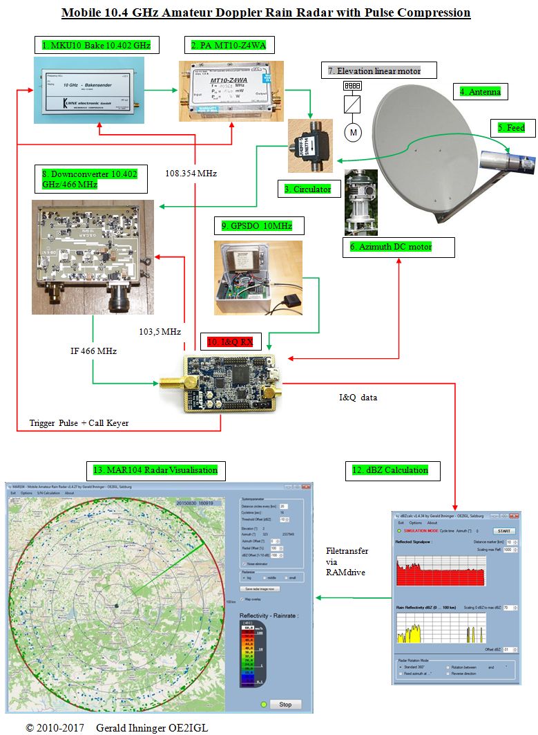
2. System overview
3. Technical details of Mobile Amateur Doppler Dual-mode Dual-PRF Rain Radar with pulse compression
Dual mode means one mode for short range (with better distance resolution) and the other for long range detection (with better dBZ sensitivity).
Frequency :
10.402 GHz, vertical polarisation
Dish diameter :
0.82 m
Dish gain :
37.0 dBi
Effective radiated power : 63 dBi
Dish beam width : 2.5 °
Dish rotation : 1 per minute
Azimuth
resolution : 0.9
°
Time per azimuth step : 125 msec
Echo time :
2/ 1.2 msec
Pulse :
100/20 µsec (long/short range)
Pulse repetition freq. : 500/850 Hz
Pulse integration : 60 x
Doppler speed up to : +/- 60 m/s
Distance minimum : 15/3 km (long/short range)
Distance maximum : 150/25 km (long/short range)
Distance resolution : 150/37 m (long/short range)
Sensitivity :
0.1 mm/h @ 120/25 km
Power consumption 12V : 36 W without computer
Weight without accu : 25 kg
Costs :
1500 ?
4. Details of used modules
10.2 - 10.8 GHz circulator
No difference to version 1 (standard pulse rain radar)
10.402 GHz dual mode horn feed
No difference to version 1 (standard pulse rain radar)
GPSDO 10 MHz
This highly stable 10 MHz reference signal feeds the SDR.
10.402 GHZ microwave transmitter
Version 2 needs a chirp TX signal for pulse compression.
OPEN: Oscillator frequency is 108.35417 MHz. For a 1 MHz sweep on 10.402 GHz I have to sweep the oscillator from 108.35417 to 108.36458
MHz (1 MHz / 96 = 10.417 kHz) by FM modulation.
Maybe an external AD9854 DDS signal generator could be also used.
4 W power amplifier
No difference to version 1 (standard pulse rain radar). Due to pulse compression TX output power looks like a 80 W transmitter.
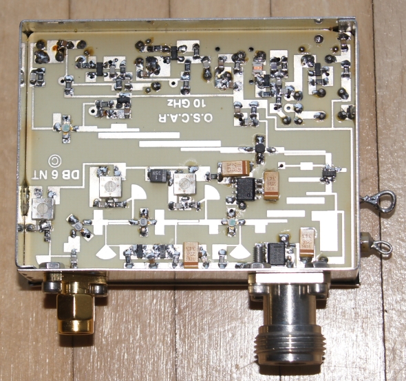
Down converter 10.402 GHz -> 466 MHz
Version 2 uses a 10 GHz downconverter kit by Kuhne DB6NT.
NF = 1.2 dB
Gain = 22 dB
SDR (software defined radio)
OPEN: Version 2 uses a digital receiver (e.g. Airspy). I&Q outputs of Airspy tuner are digitized in PIC32MZ.
The Airspy can generate a 108.354 MHz coherent signal for the microwave transmitter and a 103.5 MHz coherent signal for the down converter.
PIC32MZ µController
OPEN: Not sure if needed between Airspy SDR and Computer. As Airspy SDR has a µcontroller
it should be possible to convert PIC32 code for Airspy. Version 2 needs a faster µcontroller.
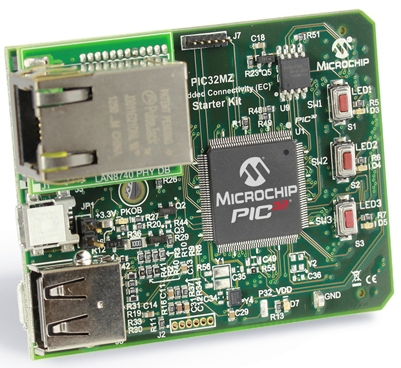
PIC32MZ starter kit with ethernet has a speed of 200 MHz, up to 18 MSPS and 12 bit ADC.
With my PIC32MX I made first tests:
- 100 MB/s TCP communication between controller and computer
- windowing (Hanning)/FFT/filter/IFFT
- speed up of some code parts (strcat, sprintf) by factor 50
Cycle timing (125msec):
- send pulse between 2 and 44µsec
- sampling every 0.5µsec for a 1ms periode (I&Q channel)
- wait 0.75 ms (switchable between 2 times)
- send next pulse and repeat this 60x (in sum 105 msec)
- signal averaging and pulse compression
- Hanning window, FFT, FIR filter, IFFT (5 msec), doppler analysis
- send TCP telegramm (1 msec)
- control azimuth rotor, display, read elevation sensor ... (1 msec)
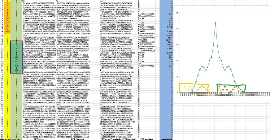
Pulse compression processing:
- Uses long frequency modulated TX pulse. This gives more TX power per pulse (higher Signal/Noise) but lower range resolution against a short TX pulse.
- FFT convolution (matched filter) is used in RX path to obtain better range resolution. Range resolution is only determined by frequency shift of modulation
and not by TX pulse width.
Example with 1 echo pulse: In this case TX pulse shape is same as RX echo pulse shape (without noise)
orange ... TX puls with
FM modulation
green ... RX echo
After FFT convolution of RX echo signal with TX pulse the result (= target detection) is shown as blue curve
with 1 sharp peak.
2nd column: TX pulse
3nd column: received echo signal
4th column: FFT of TX pulse (complex values)
5th column: FFT
of received echo signal (complex values)
6th column: Product of FFT-TX and conjugate complex of FFT-RX
8th column (blue): Inverse FFT of 6th column
Example with 2 echos within TX pulse width: Only with pulse compression we can resolve both echos.
Now there are 2 peaks and peak distance is smaller
than TX pulse width. 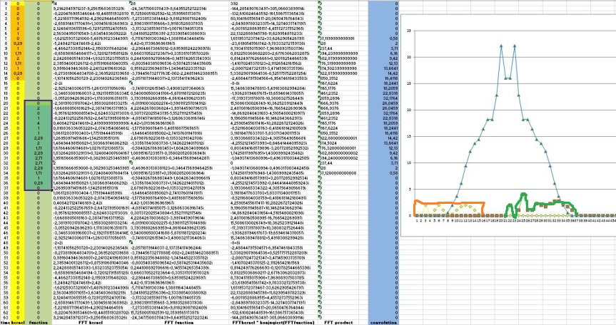
Doppler processing:
- Detecting a target in the range dimension (fast-time samples). This gives the range bin to analyze in the slow-time dimension.
- Computing the FFT of the slow-time samples (PRF) corresponding to the specified range bin.
- Identify significant peaks in the magnitude spectrum and convert the corresponding Doppler frequencies to speeds.
DC motor with encoder for azimuth (0 to 360° degrees)
No difference to version 1 (standard pulse rain radar)
5. Computer software
Version 2 uses 12 bit ADC instead of 10 bit, range up to 150 km instead of 100 km and 10 MSPS instead of 500 kSPS.
Therefore I need faster communication between µcontroller and computer. I use a TCP server (computer) - client (µcontroller) concept.
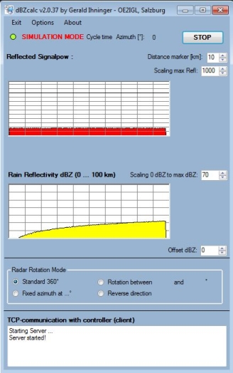
"dBZcalc-TCP" is a VB.net software running under Windows OS. µ-controller transfers 12 bit I&Q echo data to the computer.
This dBZcalc version runs a TCP server waiting for the client (controller) and receives every 125ms a telegram.
These data are buffered in a file and the second
VB.net software called "MobileRadar v1" reads this file.
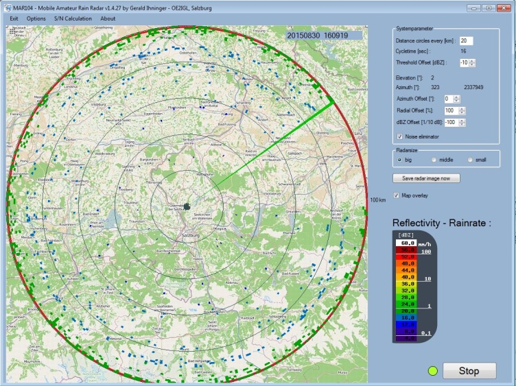
"MobileRadar v1" is a VB.net software running under Windows OS and reads data from a file created by "dBZcalc".
"MobileRadar" also converts echo data into dBZ values representing rain rate [mm/h] and makes a rain rate overlay.
No difference to version 1 (standard pulse rain radar).
Blue and green dots show background noise -> no rain
6. Tests and results
Not before 2020 whilst I am happy with my pulse radar (version 1) ;)