Ham radio stuff
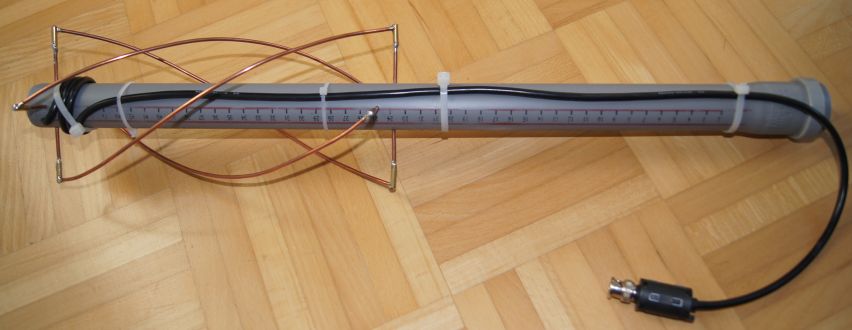
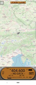
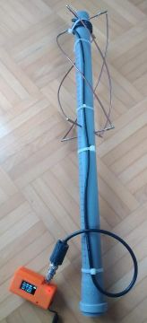
1. Weather balloons and 405MHz QFH antenna
Tried to receive a weather balloon. For more information about weather balloons, software and antennas see here.
I use a homemade QFH antenna for 15 Euro.
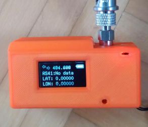
As hardware receiver I use a TTGO-Esp32-LoRa-433 MHz module. All informations and MySondyGo software can be downloaded here.
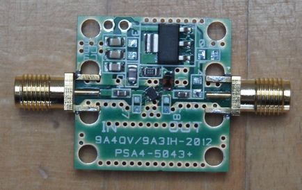
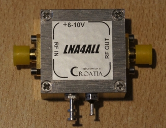
2. Low noise amplifier
LNA (LNA4ALL) from 10 MHz - 2 GHz with a noise figure down to 0.6 dB at 144 MHz and gain up
to 24 dB. It perfectly works in combination with a SDR (funcube dongle).
3. T-bias
T-bias is used e.g. between antenna preamplifier and receiver to provide power supply via coax
cable for a preamplifier.
This design (PCB) is made by F1OPA.
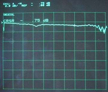
Insertion
loss: <1 dB (10 -1800 MHz)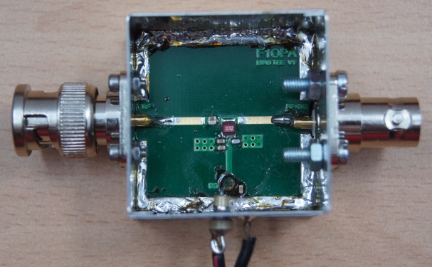
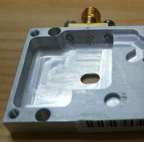
This
T-bias has SMA connectors and uses PCB and metal box by RF
Basic Store. Circuit see here
by Adam 9A4QV.
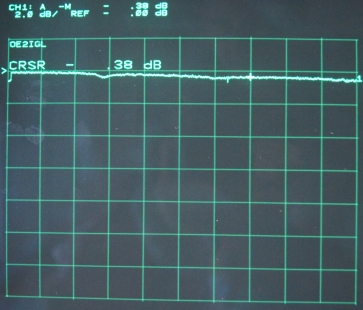
Insertion loss: <0.6 dB (10 - 2000 MHz)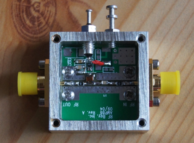
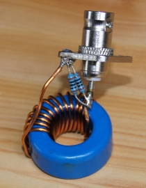
4. Probe head for noise detection
With this probe head it is easy to measure common mode and differential mode noise (e.g. power supply).
BNC connector, 50 Ohm resistor and ferrite choke.
5. LNB (low noise block) modifications I
Why?
- to test my RF test equipment
- to understand
microwave circuits
- to change it for 10.4 GHz
usage instead of 10.7-12.7 GHz
- to do the impossible
and have fun with 5? parts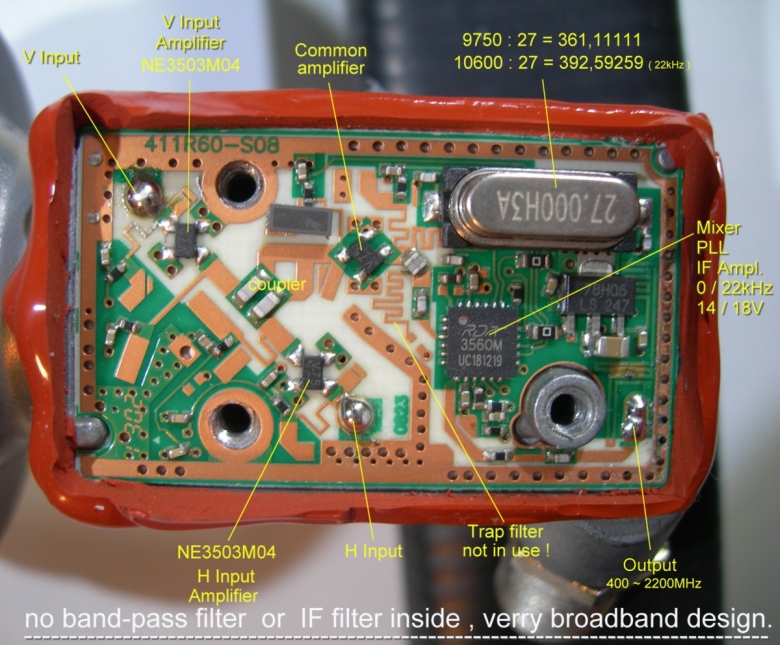
Original Octagon (OSLO) LNB by OE7DBH
Darko
OE7DBH made some modifications for amateur TV and has a lot
of stuff for sale.
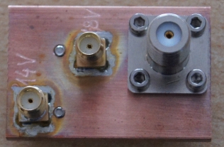
-
SMA output connector or F output connector
-
SMA input connector (horizontal and vertical)
-
additional input coupling capacitor
- 26 MHz
quartz instead of 27 MHz
- mounted on copper
plate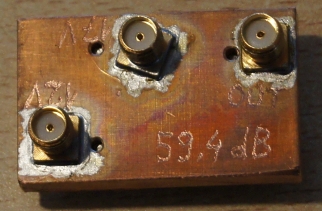
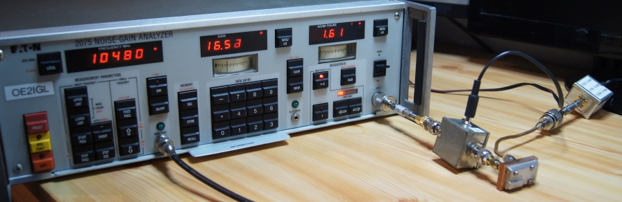
Gain
and noise figure with CANFI v2.6 and EATON 2075:
-
noise figure is around 0.6 dB at 11.5 GHz
- noise
figure is around 2 dB at 10.5 GHz and up to 3 dB at 10.368 GHz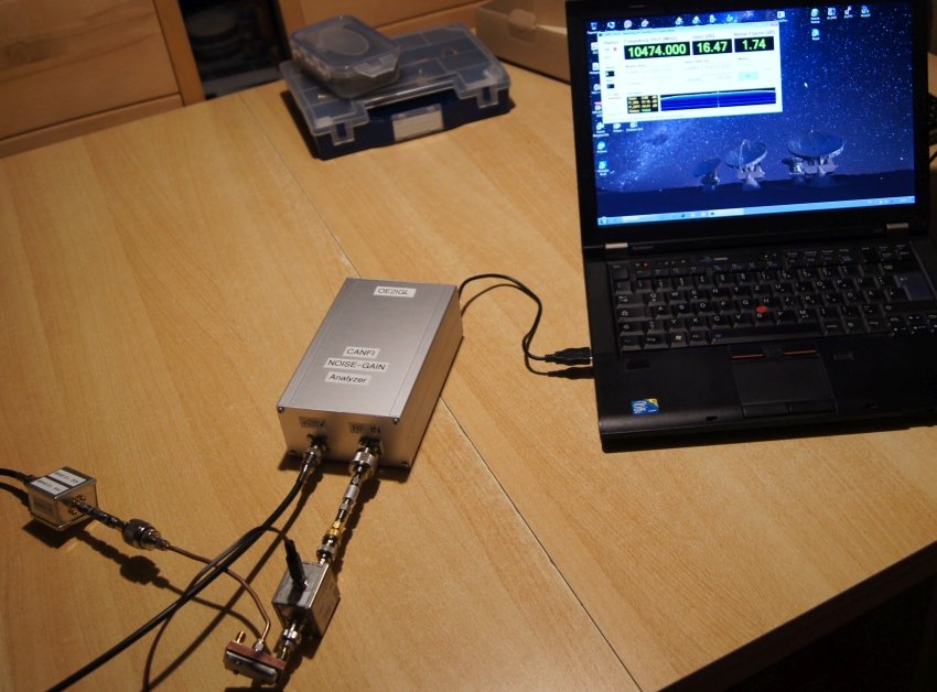
Input Return loss measurement between 8.5 and 13.5 GHz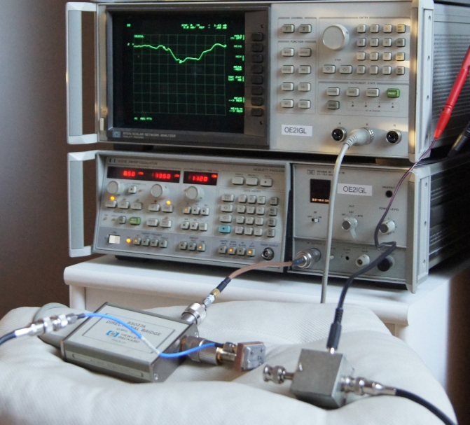
Until now it wasn't possible to trim the LNB for best noise figure at 10.4 GHz.
I tried to play with stub positions and stub length.
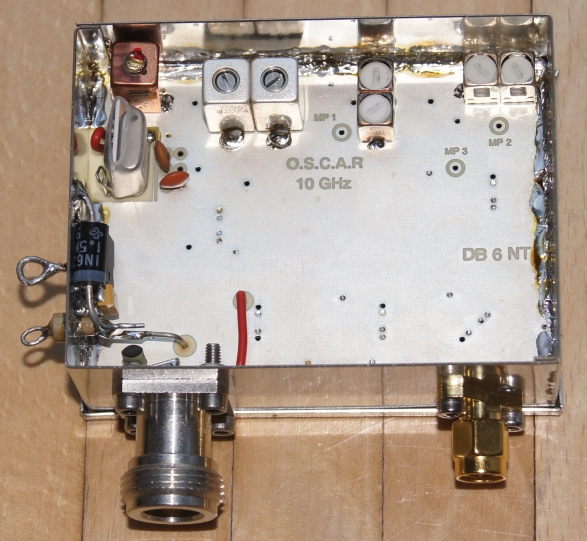
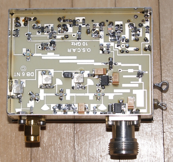
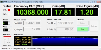
6. Downconverter for 10GHz
I ordered a 10GHz downconverter PCB made by Kuhne Electronic and all necessary parts from Eisch-Kafka-Electronic.
12V/250mA
NF = 1.2 dB
Gain = 22 dB (after
some filter improvements with stubs)
LO = 9936 MHz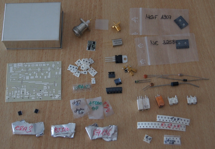
7. Sensitive RF detector
PCB is made by W1GHZ and RF detector uses power detector IC AD8307. In my case there is a 50
Ohm matched 10.7 MHZ ceramic filter in front of the detector.
With a gain factor of 1.47 it gives around 0-3300mV for a dynamic range of 90dB.
Bottom side shows input filter matching.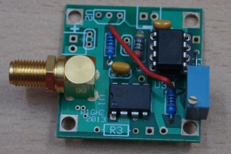
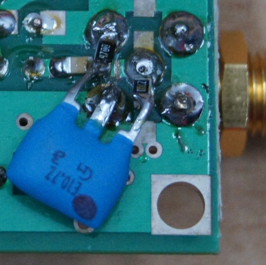
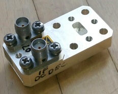
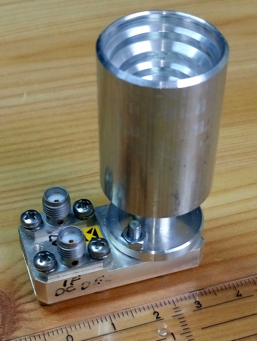
8. LNB (low noise block) modifications II
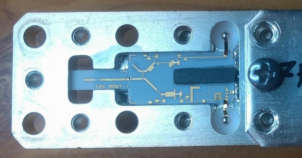
Again some modifications and tests. I used a twin Octogon LNB with PLL. Click image for full resolution.
 I cutted the track after the second IF input/output (upper right corner) and I connected this input/output via a 1nF capacitor to the 25 MHz quartz.
Now
it was possible to inject a very stable external 25 MHz via the second IF
port. I use the first IF port a standard signal port plus power supply.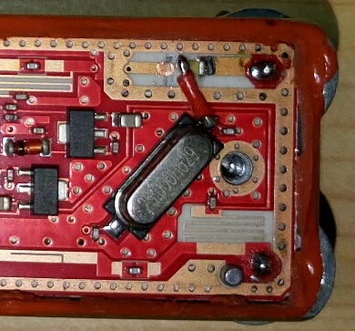
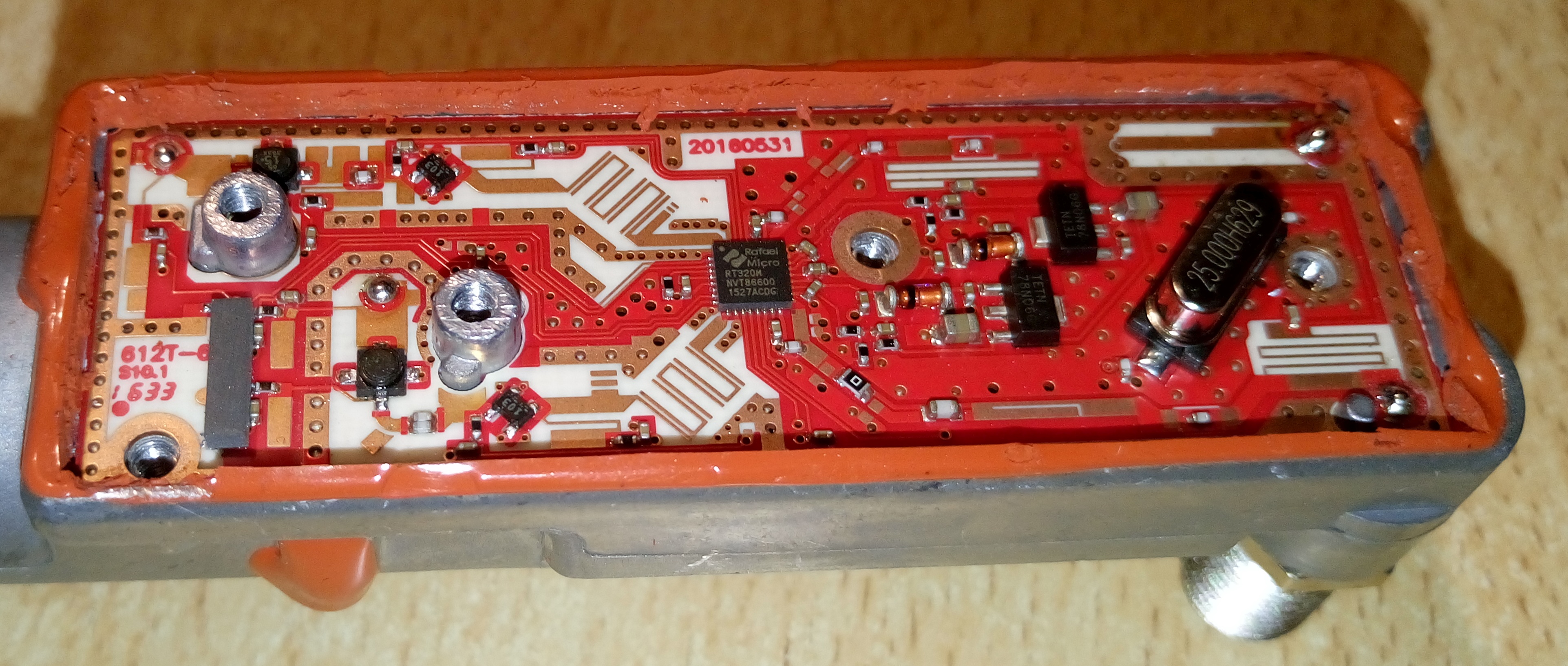
9. Amplifier for 10 GHz
For this design made by RF-Basic-Store I use a MMIC MGA-86576. Its usage is specified up to 8 GHz but
it works up to 10 GHz with a gain of 11 dB.
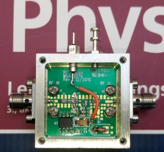
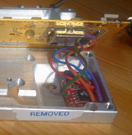
10. Modified NORT PLL for 12 GHz
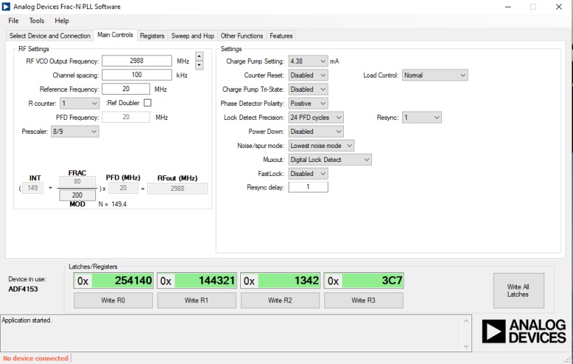
This NORT module has a connector for 12 V power supply (~260 mA power consumtion), lock signal and SPI connection. Inside there is an ADF4153 fractional frequency synthesizer and I use an Arduino
Mini Pro 3.3V to program the ADF4153 after power up. Output power is approx. 13 dBm at 11952 MHz.
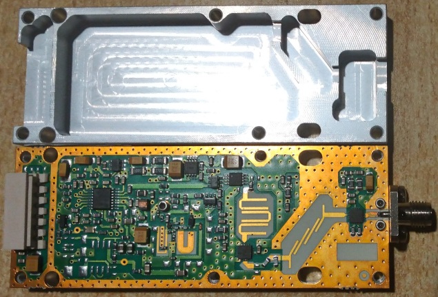
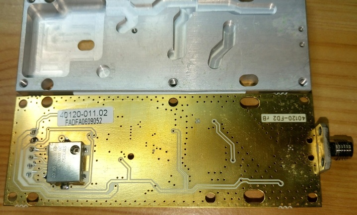
Modification:
This module has a bandwidth of approx. 500 MHz and it is possible to adjust center frequency between 11.25 and 13.25 GHz. Under the soldering point there is
a short-circuit flag (see red marked short-end stub).
Move this short-circuit flag to change frequency range. Shorter stub -> higher frequency (e.g. 12 GHz), longer stub -> lower frequency.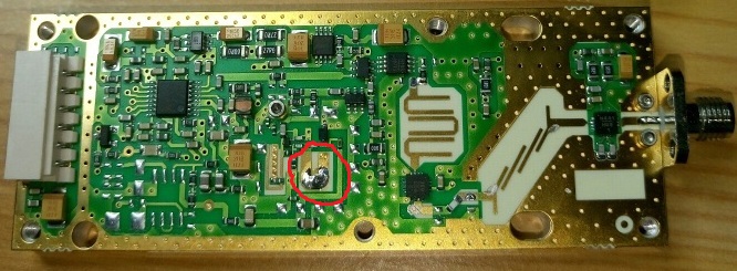
I made an external Ref-input and removed inside VCTCXO.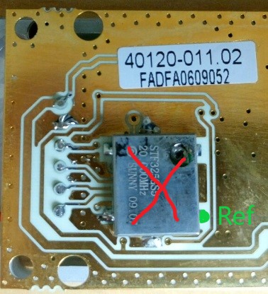
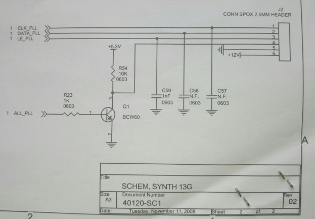
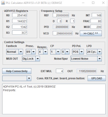
Built in PLL controller board made by OE8WOZ
Now I use a tiny controller board inside of the NORT module instead of an external arduino board. It is possible to send all ADF registers to the PLL and store these registers.
Example for my 24 GHz Transverter:
Software made by OE8WOZ:
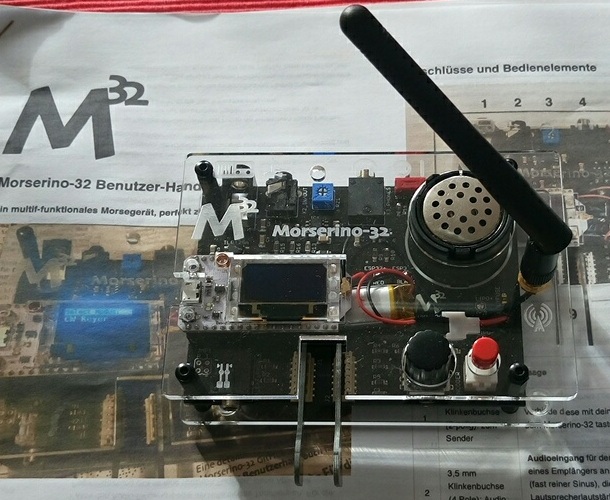
11. Morserino32
I like is Arduino based morse trainer, receiver, transmitter, ....
For more
information have a look here.
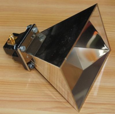
12. Horn antenna with SMA transition for 10 GHz
WR90 (=WG16) transition for 8.2-12.4 GHz with inner dimensions 22.86 x 10.16 mm. I found the horn on eBay.
13. Simple horn antenna for 47 GHz
I made this horn antenna with a step cone drill and cone angle is around 40°. Horn dimensions are calculated with PCAAD.exe

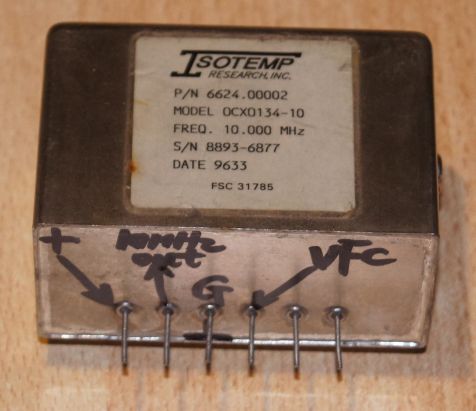
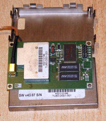
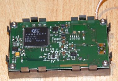
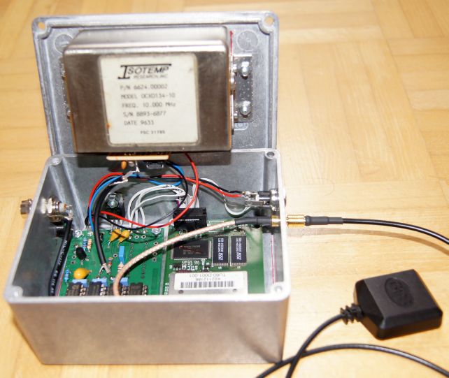
14. GPS stabilised 10MHz frequency reference
Sometimes I need a very stable 10 MHz frequency reference for my test lab equipment. James Miller G3RUH has designed such a system.
Output is a 4.8V TTL (pk-pk, Low 0/ High 4.8V) square wave (50 Ohm output). It can drive a 50 Ohm load with amplitude 2.4V pk-pk (14 dBm).
Isotemp OCXO134-10 with 10 MHz output
TU60-D120 GPS module with 10 kHz output
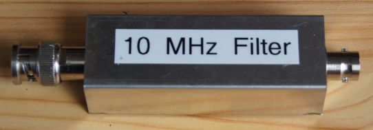
15. 10 MHz filter for 10MHz frequency reference
Most 10MHz references have a square wave. With this filter by W1GHZ
we get a clean 10MHz sine wave signal.
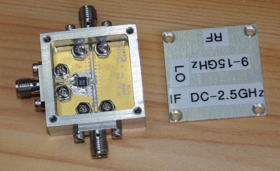
16. Passive mixer up to 15 GHz
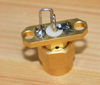
17. Multiplier up to 18 GHz
BAT15 used between ground and signal pin and a return path between pin and ground.
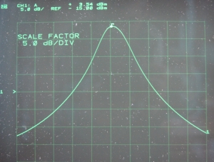
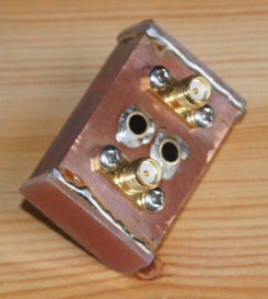
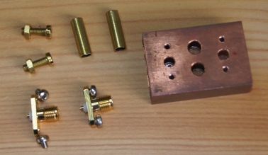
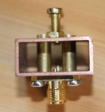
18. 10 GHz wave guide band pass filter
I built my own 2-cavity band-pass filter for 10.4 GHz by
Zack Lau (W1VT).
Insertion loss is 1.5 dB, band width is 25 MHz@3dB.
19. Alcatel detector/mixer/multiplier for 24 and 37 GHz
It is possible to use these modules as mixer (both ports), detector (only one port) or multiplier (both ports). That's perfect to detect microwave and to generate microwave.
24 GHz device: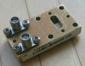
38 GHz device:
I use this device for 47 and 76 GHz.
20. GPS disciplined reference oscillator
Here I use a nice unit by Leo Bodnar.
It has 2 separate outputs (3.3V CMOS level) from 450 Hz to 800 MHz and it uses GPS reveiver for very stable output frequency. Output power is up +13 dBm.
Current consumption @ 12V DC: 190 mA
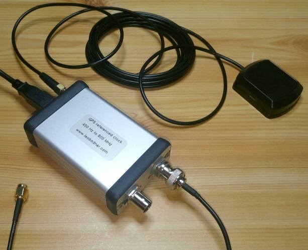
As the output signal is a square wave it is useful to use a low pass filter to make the output signal sinusoidal.
Then it is possible to connect the GPSDO output directly to a transverter to generate the LO. I use the PCBs from RFzero.
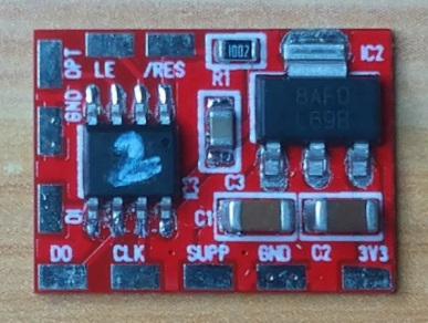
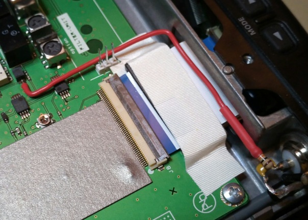
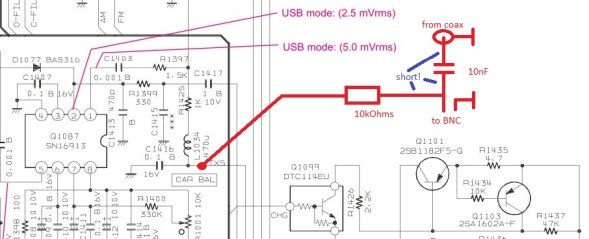
21. Modified FT-817ND
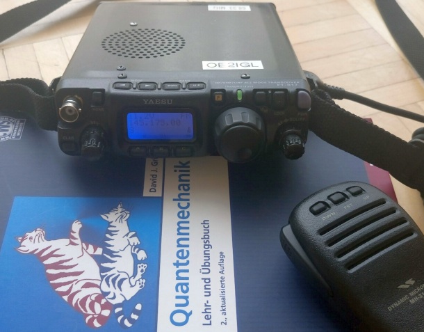
I made 4 modifications:
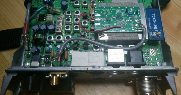
- TCXO-9 instead of factory oscillator. It is a 22.625 MHz oscillator with 0.5 ppm.
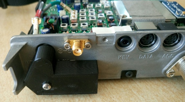
- 68.33 MHz IF output to build a panadapter with a SDR
I mounted a "panoramic adapter tap board" from SDR-Kits into the FT-817ND. At the rear side there is an adittional SMA outout providing IF signal.
- Power supply with Powerpole
- Supply +5 V to the I.F. cable for Tx switch
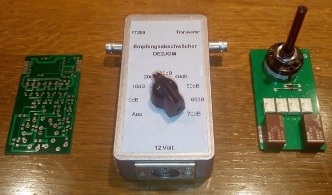
22. Rx-attenuator 0-70 dB between transverter and I.F. transceiver/receiver
At short distances Rx signal is too high. An attenuator could be used but then it is not possible to transmit. This attenuator is useable for Rx and Tx.
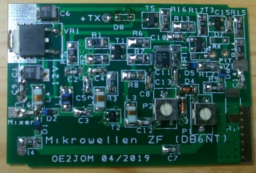
23. New important circuits for microwave transverters
Designed by Hans, OE2JOM.
- Power supply circuit board for microwave tripler module
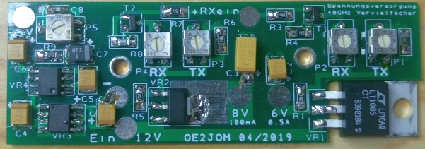
- Tx and Rx biasing circuit board for microwave mixer diode
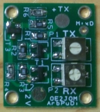
- IF amplifier circuit board
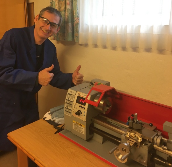
24. Lathe and boring/milling machines
This one is more mechanics than electronics but without some important machines it is not possible to make microwave parts.
It is a Holzmann Machines ED300FD_230V lathe.
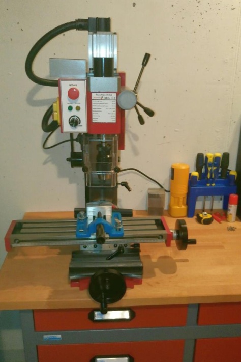
Now I have this drill/milling machine. It is a Paulimot Sieg SX2L boring/milling machine.
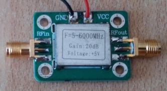
25. 5-6000 MHz broadband amplifier
I made some measurements of this broadband amplifier and it works fine. It uses a SBB5089Z amplifier chip
Power supply: +5 V
Power consumption: 70 mA
Frequency range (official): 50-6000 MHz
Gain: 15-20 dB
Noise figure: 4 dB
Output P1dB: 15-20 dBm
26. CW keyer and CW decoder via mobile phone and your RIG
Because of no need I never learned morse code. But sometimes it would be great to make some easy CW QSOs with my microwave and EME equipment.
Therfore I looked for an user friendly solution (easy and less time consuming text typing without an computer) in combination with a mobile phone.
I found "morse expert" and "web CW keyer".
Each app needs a small signal interface between phone and RIG.
IMPORTANT:
Web-cw-keyer needs full sound level from mobile phone. Use Schottky diodes with low forward voltage (<400 mV).
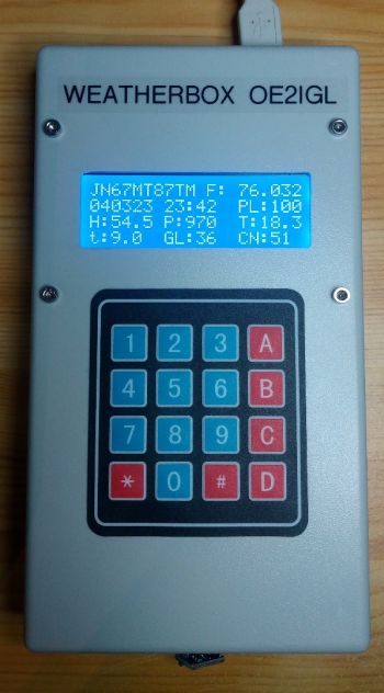
27. Weather Box for microwave link predictions
Originally designed by Barry Chambers G8AGN but I made some code changes. Using a temp, humidity, pressure sensor this device can predict S/N of any microwave link (including atmospheric loss).