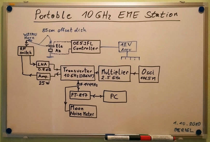
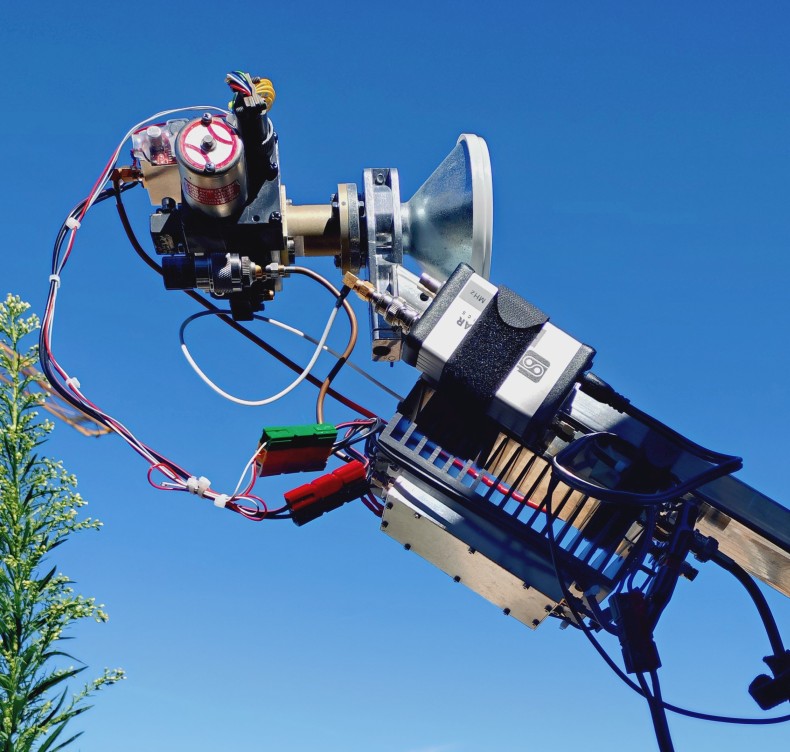
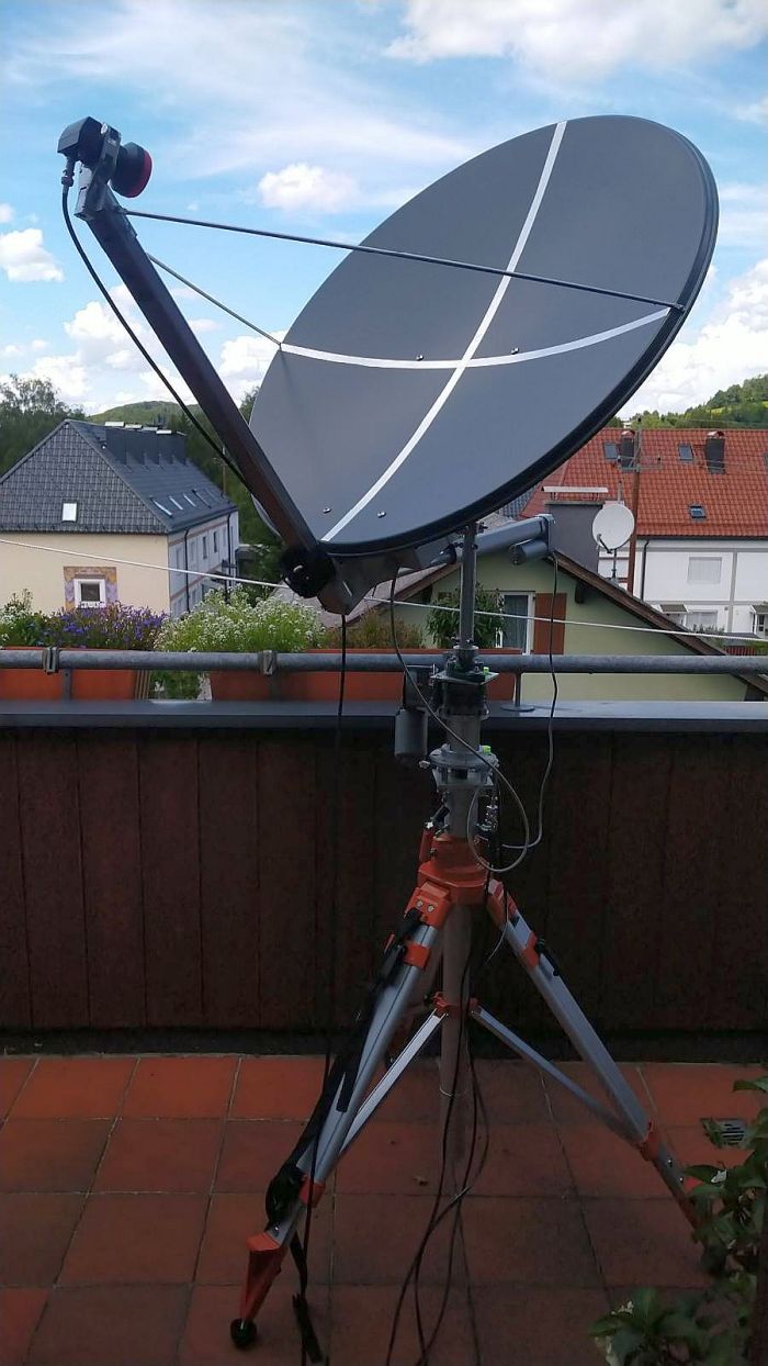
Portable, small system EME (earth moon earth) station for 10.368 GHz
As I have some experiance with my 10 GHz rain radar and microwave I want to try EME on 10 GHz. I can use nearly 70% of my 10 GHz rain radar system and Rx should be ready in short time. Again I want to build up a portable, small system. With a 82 cm offset dish, high quality preamplifier, at least 8 Watt Tx power and WSJT-X software it should be possible to get -25 dB signal-to-noise ratio (2500 Hz bandwidth reference) with high quality stations on the other end.
EARTH-SPACE ATTENUATION & SKY TEMPERATURE:
Click HERE, download and extract my Excel sheet "Earth-Space-Attenuation" to calculate microwave earth-space attenuation and sky temperatur up to 350 GHz. Calculation of atmospheric attenuation (ITU-R P.676-12) is included. Either with local weather data only or with integrated water vapour content delivered by weather sonde data.
EME link budget and analysis tool:
Click HERE
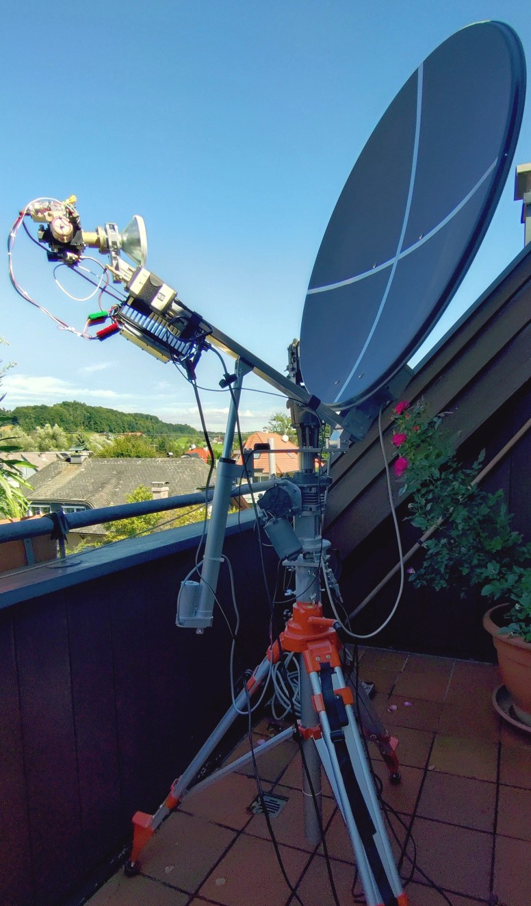
1. Offset dish with azimuth/elevation drive
Therefore I use my 82 cm offset dish with azimuth rotation system from the RADAR project.
Improved azimuth/elevation head:
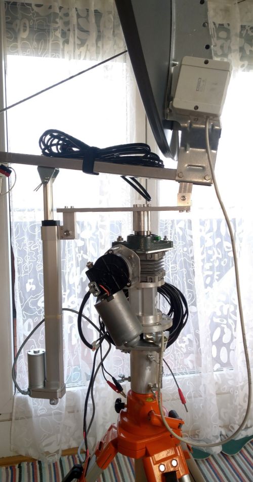
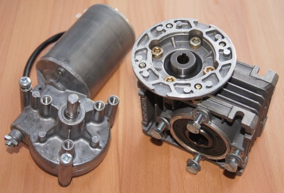
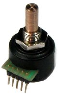
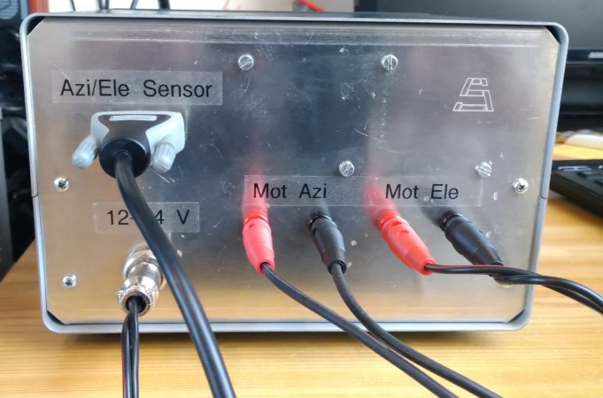
DC motor with encoder for azimuth (0 to 360°)
12V (5A, 5Nm, 40 rpm) worm gear motor (windshield wiper motor) with additional worm gear (20:1) to get 2 rpm.
Torque is approx. 100 Nm.
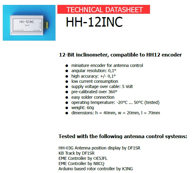
HH-12 Encoder has a resolution of 12 bit and an accuracy of approx. 0.2° (made by DF1SR).
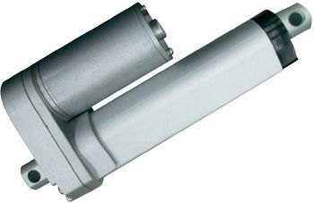
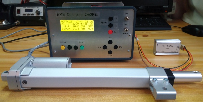
DC linear motor with encoder for elevation (0 to 90°)
Linear motor DSZY1-12-40-A-200-IP65.
Power supply: 12 V/DC
Speed: 8 mm/sec
Stroke length: 200 mm
HH12-inclinometer made by DF1SR.
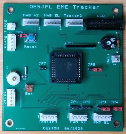
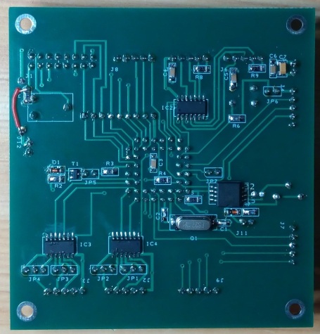
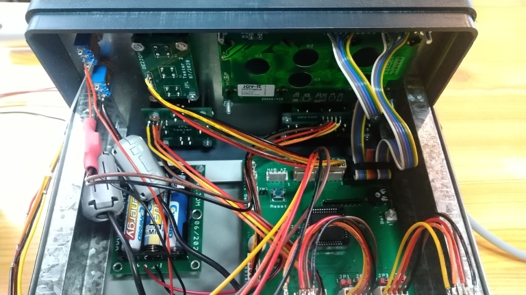
2. Dish rotor OE5JFL controller
OE2JOM made this controller board based on the OE5JFL original design and ON4BCB updated design.
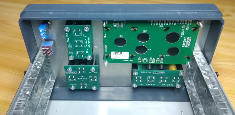
Controller housing with 20x4 LCD and push button boards:
Test of antenna controller with elevation sensor and linear motor.
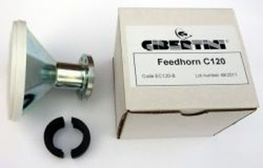
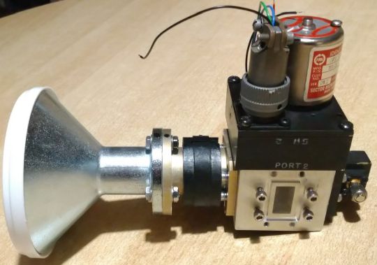
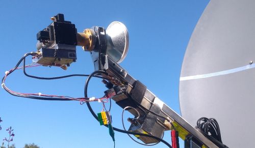
3. (W2IMU dual mode or corrugated) feed horn
Corrugated feed horn:
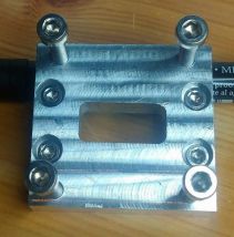
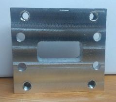
I use a special corrugated horn designed by Gibertini for my Gibertini dish. As waveguide adapter I use a circular C120 to WR75 adapter.
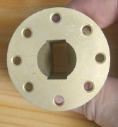
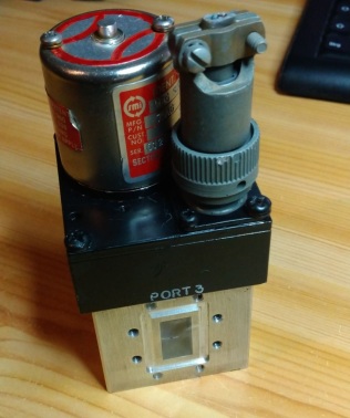
4. Waveguide switch
In front of the feed horn I mounted a WR75 waveguide switch to minimize signal loss and to have a sufficient decoupling between Tx and Rx.
So there is no need to use the SMA switch in my existing 10 GHz transverter.
Don't forget to use VERTICAL polarisation in Europe!
Current consumption @28V: max. 900 mA
I use a WR75-WR90 quarter-wave adapter plate to minimize return loss.
Thickness: 10.1 mm
Waveguide dimension: 21.1 x 9.8 mm
Radius: 1 mm
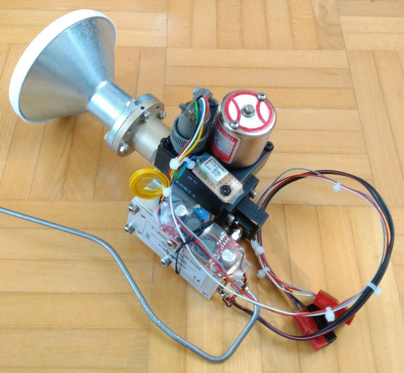
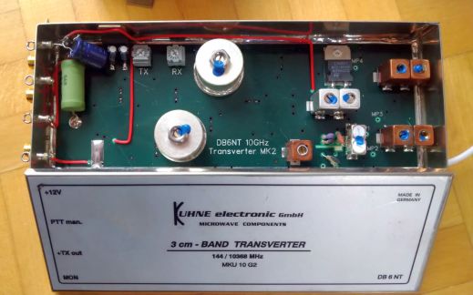
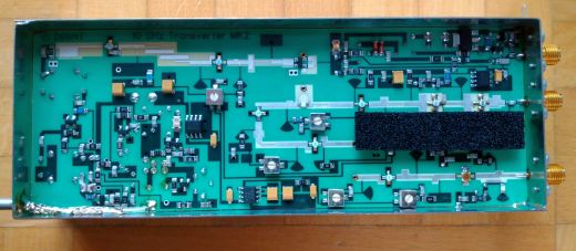
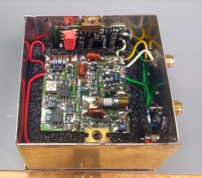
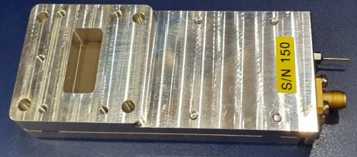
5. Transverter
A MKU-10-G2 transverter designed by DB6NT and external reference frequency. Either a 10 MHz (OCXO) or a 106.5 MHz reference for the transverter.
Current consumption @12 V: 180 mA
Noise figure : 1.2 dB
Output power @ 12V: 230 mW
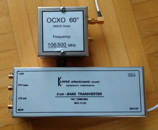
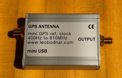
6. GPS disciplined 106.5 MHz reference oscillator to set PLL reference input
No need because the PLL has its own high stable 10 MHz oscillator. But I hate the remaining frequency offset and therefore I use a nice unit by Leo Bodnar instead of the OCXO.
It has 1 output (3.3V CMOS level) from 450 Hz to 800 MHz and it uses GPS reveiver for very stable output frequency.
My IC-705 is also very accurate (around 0.5 Hz at 100 MHz) and stable and together with the GPS stabilized transverter the system is within 10 Hz.
Output power up to 13.7 dBm
Current consumption @ 12V: 270 mA
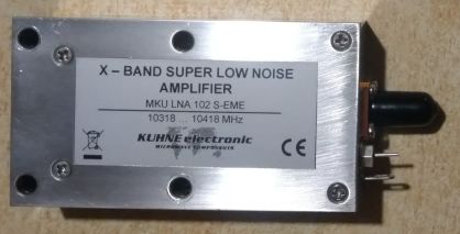
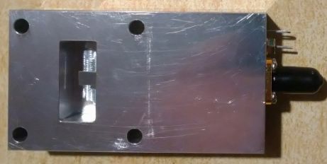
7. Preamplifier for 10 GHz
It is an EME-preamplifier made by DB6NT and it has a WR90 connection.
Noise figure : 0.64 dB
Gain: 22.9 dB
Current consumption @12V: 30 mA
I have a second preamplifier, the DU3T-XLNA.
Noise figure : 0.6 dB
Gain: 29 dB
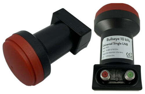
But first Rx tests are possible with a modified LNB (corrugated horn with integrated low noise amplifier and downconverter) in combination with a SDR receiver.
I use the model QO-100 Bullseye TCXO LNB (ultra stable LNB for QO-100 and Ku band satellites).
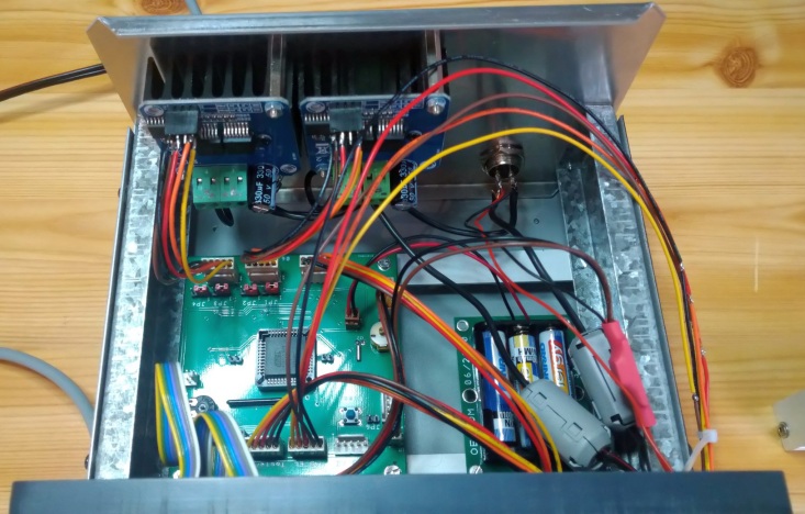
8. Power amplifier for 10 GHz with sequencer
It is a DB6NT design for 8 W (Pin = 200mW) but I use a FLM0910-3F (instead of -2F) and FLM0910-15F (instead of -8F) amplifier chip.
With some copper flags in front of 1st stage and between 1st and 2nd stage I optimized the output power. Input power is in the range of 220 mW and therefore I got only 13-14 W.
I tried an input power of 400 mW too and then I got predicted power of 15W.
Quiescent current @12V: 5.0 A
Tx current consumption @12 V: 6.0 A
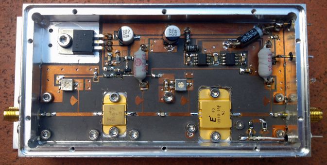
I use a SEQ4 sequencer from Kuhne electronic. It is slightly modified to use the feedback signal from the waveguide switch.
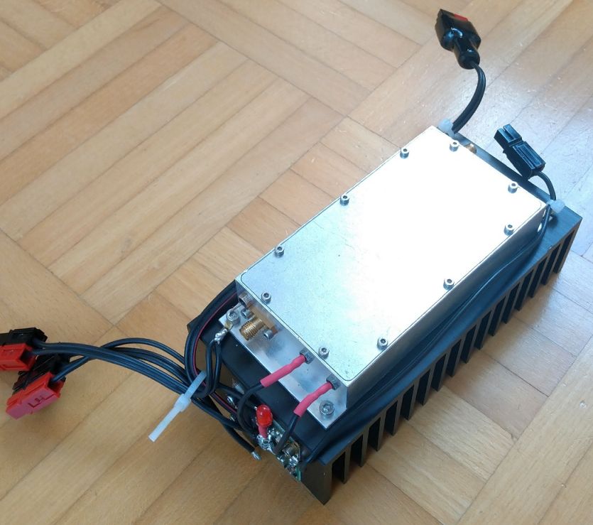
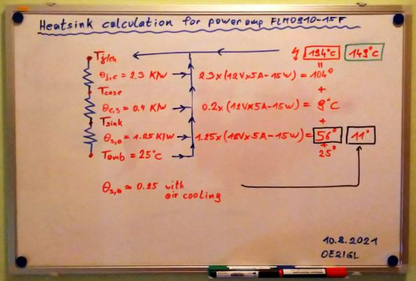
Channel/junction temperatur, heatsink and ...
The transverter - power amplifier combination is mounted under the dish feed boom very close to the feed system.
![]()
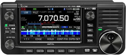
9. IF receiver/transmitter
Therefore I use the FT-817.
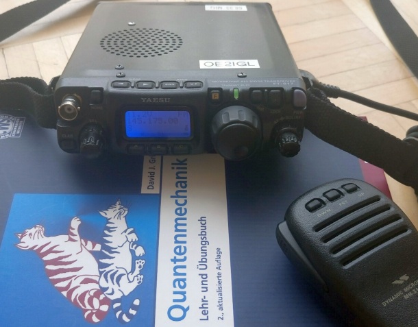
As connection between the DATA, ACC (DIN socket) and the computer I use the Digimode-4-Yaesu cable (with built-in USB sound, USB CAT control).
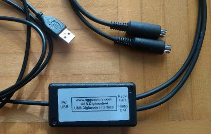
My new IC-705 will do the job in a much easier way. Only use the USB cable and connect it to a computer. I love this waterfall display.
10. Accu Pack
In this case I use a 12V LiFePO4 accu with 22 Ah because I need more than 6 A. With only 3 kg it is a lightweight.
It includes a bag, a charger, a T-plug adapter, one extra power pole connection and an additional 5 V USB output.

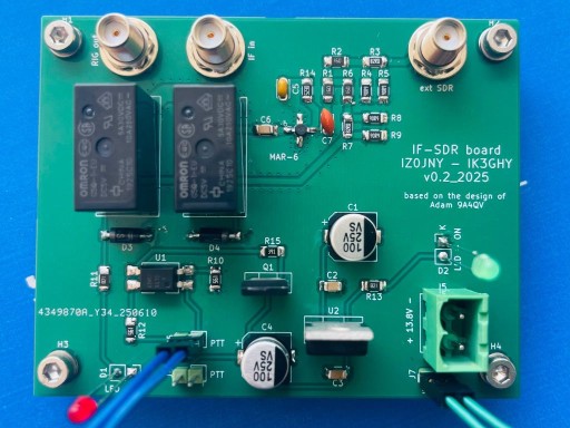
11. IF-SDR board and moon noise meter
Either I use a SDR (Airspy, Funcube dongle pro+) with Spectravue or SDR# software.
IF-SDR board, developed by Ivan IZ0JNY, is a board to split RX IF signal into 2 signals.
One for the tranceiver and one for a SDR to measure moon noise in parallel. Tx signal from tranceiver is blocked to the SDR by >50 dB.
12. Software
WSJT-X
WSJT-X, developed by Nobel prize winner in physics Joe Taylor K1JT, is an excellent software for weak signal reception.
Mode Q65 is used for 10 GHZ EME and WXJT-X can control my receiver too.
PstRotator
PstRotator works great in combination with my OE5JFL rotor controller. Now I can't only track sun and moon I can track satellites too.
![]()
13. Test results
2nd of August 2022:
I measured sun & moon noise. Therefore I used my 82 cm dish with the BullsEye LNB in combination with the Funcube Dongle Pro+ and SpectraVue.
Dish controlling was done with OE5JFL controller.
Sun Noise : 5.5 dB
Moon Noise : 0.18 dB
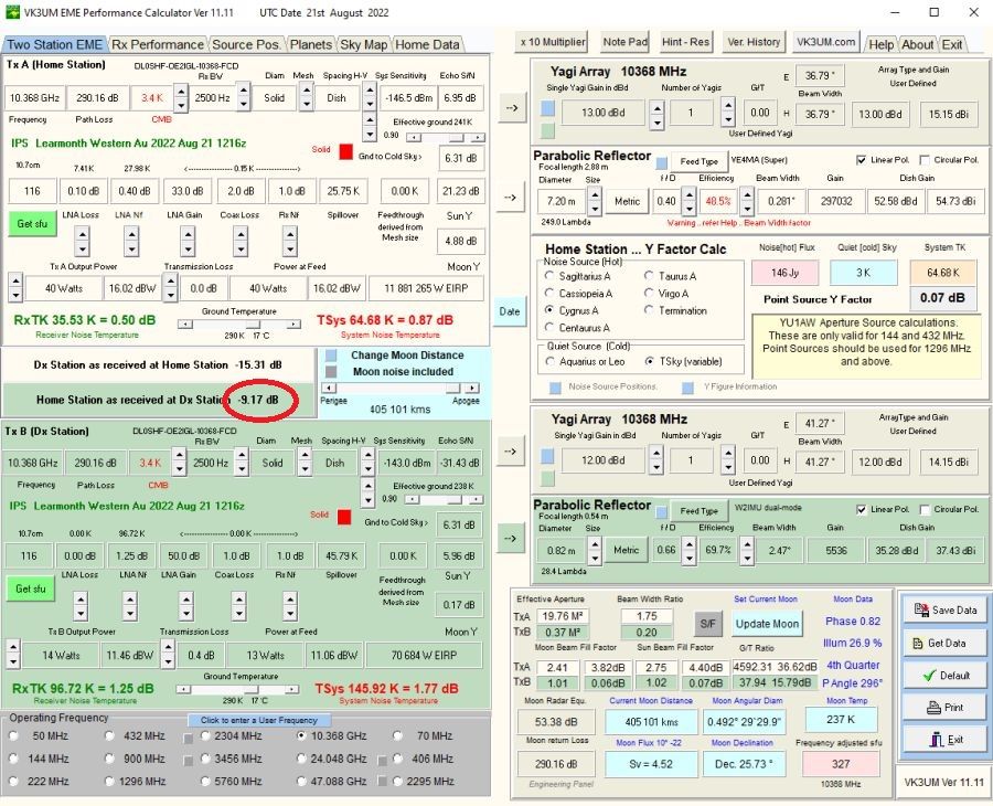
LNB noise figure : 1.25 dB (estimated with VK3UM EME Calc)
Don't forget to use VERTICAL polarisation in Europe.
3rd of August 2022:
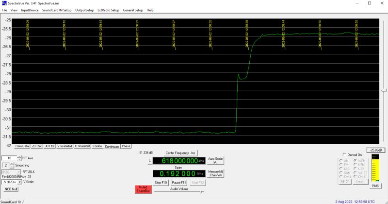
The first DL0SHF signals (CW and Q65) I saw with FCD+ and SpectraVue. S/N of CW signal was 4 dB@ 12 Hz beamwidth.
21st of August 2022:
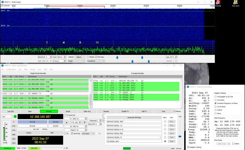
First decode of DL0SHF moon beacon with FCD+ and WSJT-X with -17 dB. It was not easy to make first decode.
At first I determined frequency shift of LNB/FCD with FCD and SpectraVue. 1000 Hz CW signal was found at 618.035 MHz, Doppler was -13.5 kHz and therefore signal should be at xx024 kHz - 13.5 kHz = xx010.5 kHz.
That means that Rx frequency was 24.5 kHz too high! So I set Rx 10368.024 MHz and IF = 9749.9755 MHz in WXJT-X to compensate this shift.
CW signal was not really visible because of frequency drift but then I had first Q65 decode. Because of additional 3 dB decode loss with an FCD the signal was not as good as could be (
see Bob Atkins KA1GT).
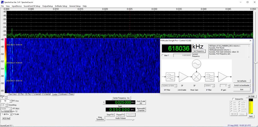
EME calc shows S/N = -9 dB. In addition the fill loss (4-4.5 dB for Gauss-Tophat-Gauss system) and 3 dB FunCube Dongle loss must be taken in account.
S/N = -9.2 - 4.3 - 3 = -16.5 dB
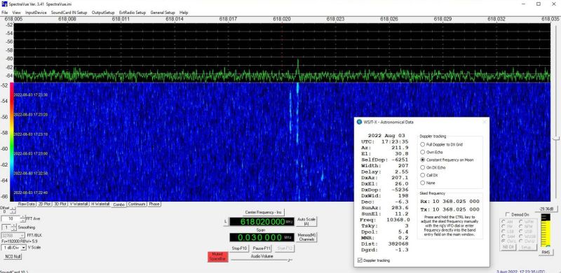
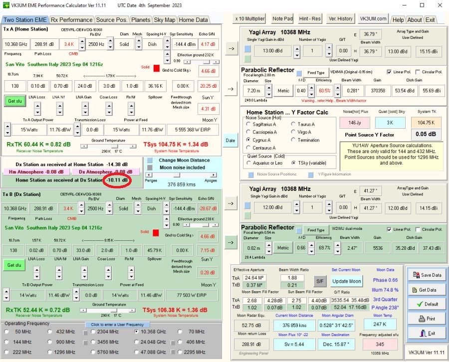
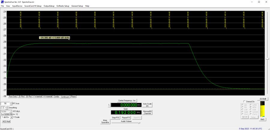
4th of September 2023:
Sun and moon noise measurements with FCD/DB6NT preamp/WG switch/improved feed and SpectraVue:
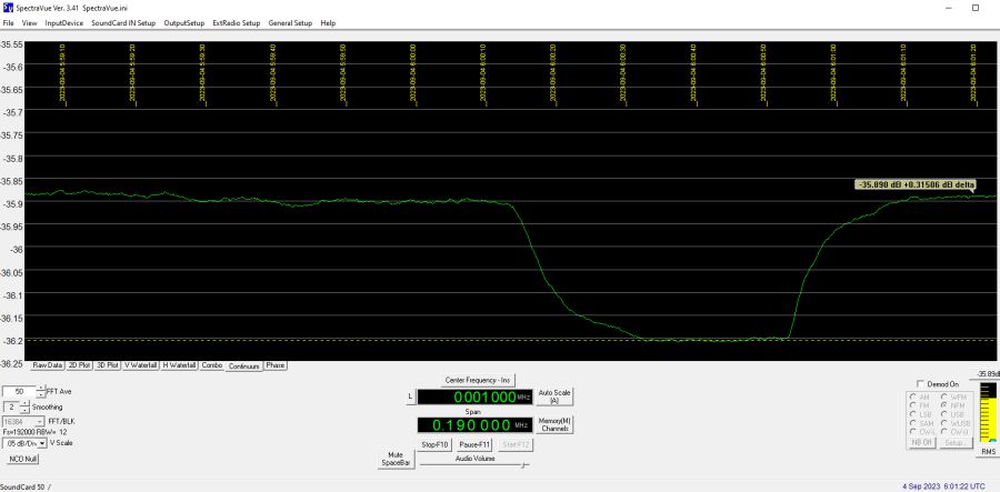
UTC 06:04 @elevation 36°, 15°C: Tmoonnoise/Tsky = 0.31 dB
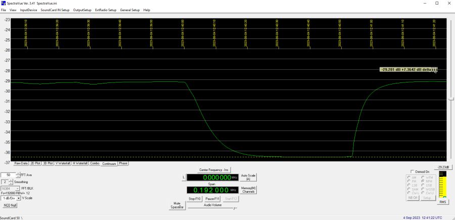
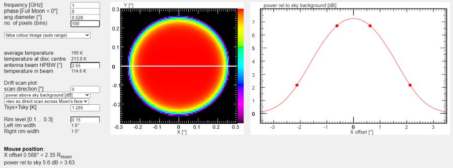
UTC 12:40 @elevation 44°, 23°C: Tsunnoise/Tsky = 7.36 dB, SFU 314 @10368 MHz
UTC 13:00 @elevation 44°, 24°C: Tambient/Tsky = 5.32 dB
All 3 measurements show a system noise figure NF = 0.69 dB and antenna efficiency of 69.0%
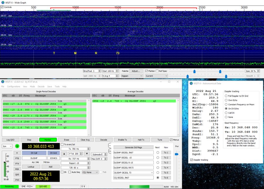
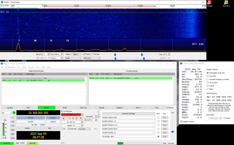
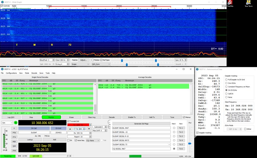
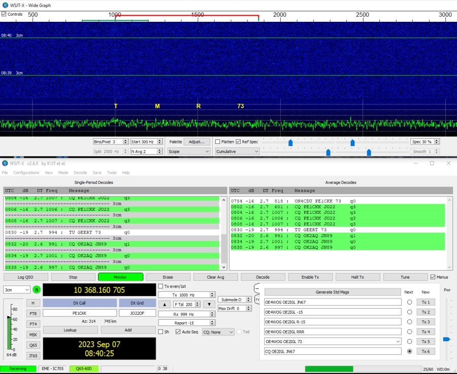
DL0SHF moon beacon decode test with IC-705/DB6NT preamp/WG switch/improved feed and WSJT-X.
At first I determined signal offset in my system with FCD and SpectraVue. It was about 15 kHz too high. That means the IF is 10223.985 MHz instead of 10224 MHz.
Then I switched to WSJT-X using the correct IF.
CW and Q65-E were visible and Q65-E decode showed S/N = -13 dB (best decode was -12 dB).
I should mention that at the moment DL0SHF 10 GHz beacon uses around 15 W (4 dB lower than standard).
My EME link budget & analysis tool show S/N = -12 dB. That's a really good match.
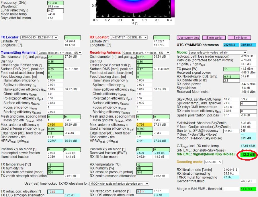
In comparison: EME calc shows S/N = -10.1 dB. In addition the fill loss (2.0 dB for Gauss-Tophat-Gauss system) must be taken in account.
S/N = -10.1 - 2.0 = -12.1 dB.
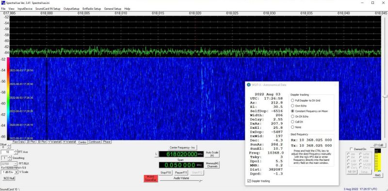
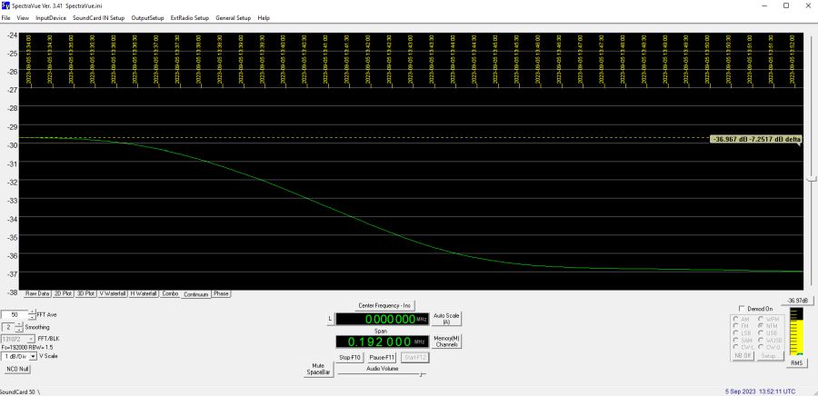
5th of September 2023:
Again some WSJT-X decodes. This time with reference spectrum and fine tuning of feed position.
Most decodes with S/N -10 dB (one with -9 dB). But this is not correct! If start tone is below 600 Hz then S/N is (calculated) better, in reality it is still -12 dB as the day before.
UTC 05:11 @elevation 55°, 12°C/80%: Tmoonnoise/Tsky = 0.32 dB
UTC 11:43 @elevation 48°, 23°C/55%: Tsunnoise/Tsky = 7.54 dB, SFU 322 @10368 MHz
UTC 05:25 @elevation 52°, 12°C/80%: Tambient/Tsky = 5.38 dB
All 3 measurements show a system noise figure NF = 0.69 dB and antenna efficiency of 69.0%
Best sun noise was 7.54 dB (stable over longer time).
I made a sun drift from max sun noise to sky noise (about 5°). Together with the curve of the sun drift and Joachim's sun drift tool I was able to determine the HPBW of my 0.815 m antenna.
7th of September 2023:
Because the DL0SHF moon beacon is out of order I needed a plan B. Before I installed a GPS stabilized frequency reference for the transverter (106.5 MHz).
Then I used the HB9Q logger to find some transmitting 10 GHz EME stations. After checking for maximum moon noise I tried to decode some of these stations.
It worked and I had decodes between -16 dB and -23 dB.
17th - ??? of September 2023:
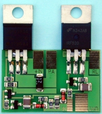
I mounted the power amplifier piggyback on the transverter.